
Activation via license key
Window constructions – Plugin
€94,50 *
(Recommended regular price – no special offers available)
– All prices are incl. the statutory VAT.
Module for Unrestricted Window Design
The additional module for window construction allows you to create your own window constructions for further use in your planning. In addition, ready-made window constructions can be loaded and modified.
When you create a new construction, you must first specify the type of construction, at the moment only “New Window Construction” is available. In future the module will be expanded to include door and façade construction.
Once the construction grid has been automatically or manually defined, you can create the profiles within the grid. At the moment, three profiles are automatically created for each window construction – the frame, the casement (frame) and the lattice profile.
If you require more than the default profiles in your window construction, you can simply define new ones. For instance, you could define various casements with different casement frames or different lattice profiles.
This module is included in the following cadvilla versions
Features of Window Construction
 By default, a grid is created with 3×3 fields. This grid can be extended and modified according to your own requirements.
In the section for grid lines, you can select a grid line and change the dimensions to the next grid line. These dimensions can be changed for horizontal and vertical grid lines. Therefore, you can use the grid to create a basic framework which defines the dimensions of the window construction.
It is possible to construct casements which span several grid fields. However, in general a casement should be contained in a single grid field, in order to simplify future changes to the grid or the casement.
 All components of window construction except for the filling are based on profiles.
Therefore, it is possible in the future to include also profiles from window manufacturers and to use these directly.
Currently, three profiles are created automatically for each window construction – the frame, the casement (frame) and the bar profile. The dimensions of these components all derive from these profile types.
If for example you wish to change the width of the frame, then open the construction properties dialog and change the width of the frame profile accordingly. If you require more than the standard profiles in your construction, then simply create a new profile. This way you can use various casements with different casement frames.
Any changes to the dimensions of a profile automatically affect all components used by the profile.
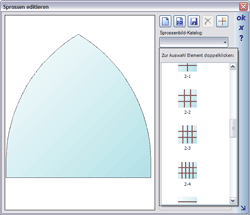
 A casement selected from the basic types available can be positioned within the grid by putting in a rectangle where the selected casement is automatically created. The direction in which the rectangle is put in is irrelevant. You can combine different types of casements to create the desired window. For certain shapes, e.g. semi-arch, the casement must be subsequently mirrored to create ‘an arch’ from two semi-arches.
Each type of casement has specific properties, which can be modified using the appropriate properties dialog. You can find additional settings for the casement parameters, style and filling in the lower part of the dialog. The style of casement is reflected first of all in the construction view, and is taken into consideration by the planning software later.
The various parameters for casements are illustrated by diagrams in the planning software dialog.
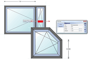
The software differentiates between grid and frame parameters. These parameter settings affect the variable part of the grid or frame. A grid parameter affects the part of the grid where it was put in, and a frame parameter affects (makes only sense for the polygon casement type) the frame.
Grid parameters change the dimensions of the grid lines where they are put in, and thus form a variable part of the construction. For instance, if you have a grid with two fields, each 1 m wide, and you put in a parameter for the left field setting its width at 1.5 m, then the width of both fields is changed. The left one to 1.5 m and the right one to 0.5 m because the overall size of the grid remains unchanged.
Frame parameters are an input aid for polygonal casements. In the following example the final shape of the casement shown was formed using the frame parameters.
The functions for ‘bars’ can be divided basically into two categories:
- Creating and saving bars and bar arrangements
- Allocating and using bars
Bars are always allocated to a casement. The allocation is performed over the context menu of a selected casement or over the properties dialog of a casement.
When a bar has been positioned, you can change its position numerically and at the same time specify whether the value is fixed. If a value is not defined as fixed, the position of the bar will change if the casement size is changed.
Another way to create bar arrangements is by drawing a 2D symbol using the drawing functions of the 2D graphic feature.
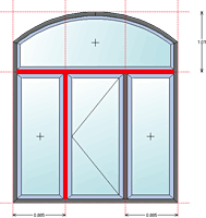 Casements are always adjoining because the window frame is created exclusively based on the exterior contour of the complete construction. Nevertheless, it may be required that the window construction is divided horizontally and/or vertically. This can be done using mullions and crossbars which can be put in on the grid between casements. Mullions and crossbars have no special properties apart from a profile which defines their width and thickness.