


In cadvilla, you can effortlessly create individual and highly customized wall openings, such as an elegant round arch, by utilizing a precise polygon input directly within the wall section view. This comprehensive tutorial will systematically guide you through the process of setting up the necessary construction guidelines, defining the exact architectural geometry, and successfully cutting the custom recess. Furthermore, you will learn how to arrange your workspace layout to seamlessly monitor the 2D floor plan and the 3D model simultaneously. Ultimately, mastering these geometric polygon tools will significantly elevate the detailing and precision of your 3D architectural projects.
Note: Some of the advanced functions shown in this video tutorial might not be included in the basic “cadvilla basic” version.
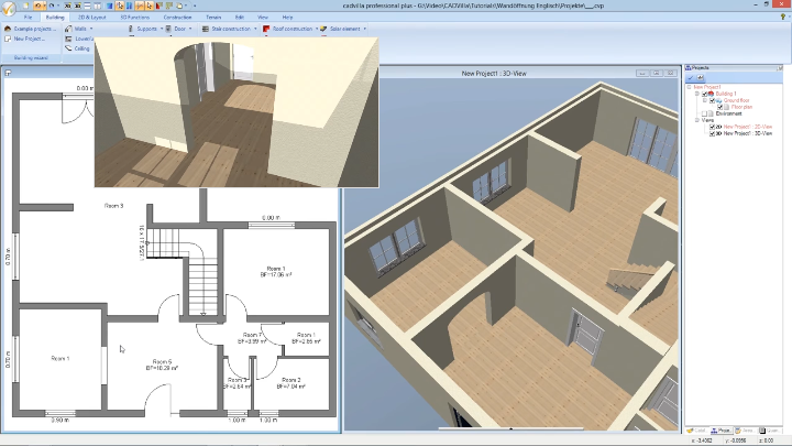
1. Generating the Wall Section View
[01:24] Creating the Frontal Wall Section To draw the exact shape of your desired recess accurately, we first require a direct frontal view of the specific wall.
- Deactivate the grid (
Grid off) and the line width (Line width off) to be able to snap and orientate yourself better.

- First, hover your mouse cursor in the 2D view exactly over the wall where the visual opening should be created.
- Next, carefully move the cursor close to the specific wall side from which you inevitably want to generate the view. As soon as you select the wall, it will intuitively be highlighted in red, and the chosen side will be marked distinctly with a red geometric line.
- Click the
left mouse buttonto formally select the wall. - Following that, press the
right mouse buttonto open the context menu and explicitly selectCreate wall section. - Consequently, the new detailed 2D section view opens automatically. Finally, press the
ESCkey to terminate the active selection correctly.
[02:47] Arranging the Workspace Vertically
- Tip: To maintain a perfect project overview, you can neatly arrange the different floating windows side by side. Simply navigate to the top menu, select
View, and click onVerticalto comfortably monitor the 2D layout, the 3D rendering model, and the wall section simultaneously.
2. Constructing the Exact Guidelines
[03:12] Placing Guideline: For drafting the exact geometric shape of the round arch without errors, we highly recommend the usage of structural guidelines.
- First, navigate efficiently to the
2D Layoutmenu, proceed to2D Guidelines>Guideline, and selectCentered guideline. - Next, carefully draw a vertical center line to successfully define the absolute middle axis of your future round arch.
- Furthermore, utilize the
Numeric parallel guidelinefunction (accessible via the convenient shortcutP) to accurately establish the horizontal limitation lines representing both the desired width and the total height of your wall passageway.
[05:19] Creating the Guide Ellipse: For effectively constructing the architectural arch curvature itself, a supplementary guide ellipse is perfectly suited.
- Therefore, navigate to
2D Layout>2D Guidelines>Guide ellipseand click on the specificGuide Ellipse (Centre and Corner Point)tool. - Finally, align this geometric circular shape perfectly by snapping precisely to the designated intersection points of your previously drawn linear guidelines.
3. Inserting the Wall Cutout via Polygon
[06:04] Defining the Polygonal Opening: Now, the actual physical visual opening will be systematically generated within the 3D model.
- First, navigate precisely through the main menu by selecting
Building>Cutout>Wall cutoutand finally chooseInsert with polygon. - IMPORTANT: When entering the geometric wall cutout, it is absolutely crucial that the initial starting point, as well as the final endpoint, are securely located entirely within the solid wall area. Specifically, your cursor tip must be positioned strictly inside the wall surface when snapping to the guideline intersections; otherwise, the software will forcefully display a warning error message.
- Next, casually trace the carefully constructed contour of your intersecting linear guidelines and the curved round arch using your active polygon tool.
- Finally, after meticulously placing the very last coordinate point, terminate the active polygon input by executing a
right-clickand selectingComplete.
4. Final Completion and Cleanup
[07:55] Finalizing the Round Arch The beautifully constructed round arch is now successfully completed and instantly visually apparent within your 3D view.
- First, simply press the
ESCkey to completely exit the active polygon mode. - Next, the previously generated frontal wall section view is practically no longer required and can effortlessly be closed.
[08:14] Deleting the Section Symbol
- Furthermore, an automatically generated graphical section symbol remains visible inside your main 2D floor plan. If temporarily or permanently not needed, you can simply select it with a single left mouse click and cleanly remove it by pressing the
Deletekey on your keyboard. Ultimately, confirm the prompt withYesto finish the cleanup process.