

Do you need to create an excavation pit or prevent the terrain from cutting into your building? In this tutorial, you will learn how to use subtraction solids in cadvilla to achieve exactly that. First, we will show you how to define the initial shape using an extrude solid via polygon. Afterward, you will discover how to convert it into a subtraction solid and configure the intersection properties correctly. As a result, you can perfectly recess your building into any terrain without graphical glitches.
Please note: Some of the functions shown in this tutorial are only available in the product versions “cadvilla professional” and “cadvilla professional plus”.
Below is a detailed overview of the video’s content.
1. Define an Extrude Solid
[00:49] General Explanation on Using Subtraction Solids
- Subtraction solids are used, for example, when a terrain goes through a floor of the building and is not automatically recessed because rooms are not fully closed or due to other special architectural situations.
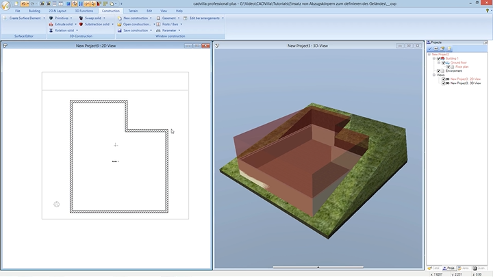
[01:16] Prepare the View and Select the Extrude Solid
- In the first step, deactivate the
Gridand theLine width on/offin the2D-Layouttab to get a better overview and to make snapping easier.

- Make sure you are in the 2D view. Activate the floor that should contain the subtraction solid (e.g., your ground floor).
- In the top menu, select
Construction>Extrude solid>Insert with polygon.
[02:22] Determine the Base Level and Properties
- Click with the left mouse button inside your building in the 2D view to select a surface for plane definition.
- Afterward, press the right mouse button and select
Properties. - In the newly opened window, switch to the
Extrude solidtab. - Under
Parameter, enter a value for theHeight(e.g.,6meters). Base this value on the highest point of your terrain. Confirm the settings withOK.
[03:21] Draw the Polygon
- Now, start defining your polygon on the outside of your external walls by clicking the corner points one by one.
- After selecting the last point, press the right mouse button and select
Complete. - Note: Please ensure that the edges of the extrude solid do not perfectly overlap with height points, height contours, or other terrain elements like paths or terraces.
2. Convert to Subtraction Solid and Define Intersections
[04:12] Convert the Solid
- Select the newly created extrude solid in the 2D view.
- Right-click on it and select
Convert to subtraction solid. - Consequently, the volume changes its appearance to translucent red. Press the
ESCkey to clear the selection.
[04:30] Define Intersections
- Select the translucent subtraction solid again, press the right mouse button, and open the
Properties. - Go to the
Intersectionsection to define what exactly should be cut away. - For the first rule, open the
Select objectsdropdown, click onon unselected layers, activate theEnvironment, and uncheck theFloor plan. - Then open the
Select typesdropdown and deselect all options except forTerrain. - Note: In the video, the narrator adds another rule: For
Select objects>on selected layers, uncheck theFloor planand check theEnvironmentagain. Then underSelect types, uncheck3D-Constructionswithin the3D-Objectsfolder. - Confirm all your intersection settings by clicking
OK. The terrain is now cut out correctly.
3. Adjust Visibilities and Move the Solid
[06:19] Hide the Subtraction Solid in 3D
- Switch to the 3D view to check the result. The red block might still be visible.
- To hide it, right-click anywhere in the 3D view and select
Visibility. - Open the folder
3D-Objectsin the dialog window. - Uncheck the point
3D-Subtraction solidsand confirm withOK. The physical solid is now invisible, but the cut within the terrain remains active.
[07:20] Move the Subtraction Solid in Height – Create a Section View (Optional)
- If you want to change the height or vertical position of the subtraction solid later, the easiest way is to use a section view.
- Go back to the 2D view. Select
View>New section viewand draw a section line through your building to open the specific view window.
[08:44] Move the Subtraction Solid
- Within the new section view, select the outline of the subtraction solid with a left mouse click.
- Press the shortcut
Ror choose the functionMove with reference point. - Click on a reference point of the solid and drag the body up or down to correct its height. Ultimately, press
ESCtwice to finish the action and close the section view.