

Hier ist der übersetzte und für Yoast SEO optimierte Text auf Englisch. Er basiert auf der strukturierten und gut lesbaren Version, die wir gerade erarbeitet haben.
Tutorial: Import 2D DWG and 2D DXF files
Importing 2D DXF and 2D DWG files serves as the ideal digital blueprint for your projects in cadvilla. Since these vector formats do not contain 3D component information, you use the drawings as a precise template for tracing. In this step-by-step guide, you will learn how to import the files correctly, set the right scaling factor, and build your 3D model efficiently.
1. Basics of 2D import
- Pure 2D vector format: The files exclusively contain X/Y coordinates. They lack height information (Z-axis) as well as component properties (the software does not know what a wall or a window is).
- Digital blueprint: You place the imported drawing in the project and simply trace the real 3D elements (walls, windows, etc.) over it. The 2D lines serve as practical snap points.
- Define floor heights: You set the heights of the respective floors separately via the floor properties (Right-click on the floor >
Properties). - Model terrain: Always set elevation points for the terrain relative to a defined zero level (e.g., a corner on the ground floor). Do not base this on the absolute height above sea level.
2. Step-by-step guide to importing
- Start import: First, create a new 2D view. Then click the
menu(cadvilla Logo,top left corner) >Import>2D DXF/DWG files. - Select file: In the
Open 2D-Symbol filedialog window, select the desired file with a double click. - Adjust layers: In the import window, you can show or hide individual layers in the
Layersarea. The preview updates immediately. - Check scaling: If the drawing is not completely visible in the preview, adjust the scaling factor. Click on
Import optionsand enter a value like0.001underFactor. Click in a free area to update the preview, and confirm withOK. - Place drawing: Place the file in the 2D view with a left mouse click and then press the
ESCkey. - Move to own layer: Create a new layer (Right-click on the
Ground floorlayer >New layer). Assign a name and confirm withOK. Then select the imported drawing, right-click, and chooseMove to>[Name of the new layer]. - Check scale: Select the drawing, right-click, and choose
Adjust scaling. Click two points whose exact distance you know. Correct the displayed target length if necessary and confirm withOK. - Trace walls: Select
Building>Walls>External wall>Numeric polygonal input. Adjust the wall thickness to match the template via Right-click >Properties. Now trace the walls. Use the key combinationCTRL+Wto change the reference side (reference point) of the wall while drawing. - Completion: After entering all walls, windows, doors and more you can simply deactivate or delete the layer containing the 2D DXF/DWG file.
3. Finding the correct scaling factor
The data in 2D DXF/DWG files often contains dimensions in centimeters or millimeters instead of meters. You can recognize this immediately after importing:
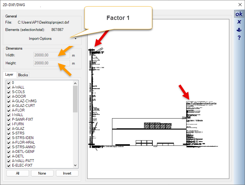
- Factor 1: If texts overlap and dimensions are extremely large (e.g., 20,000 m), the factor is clearly too large.
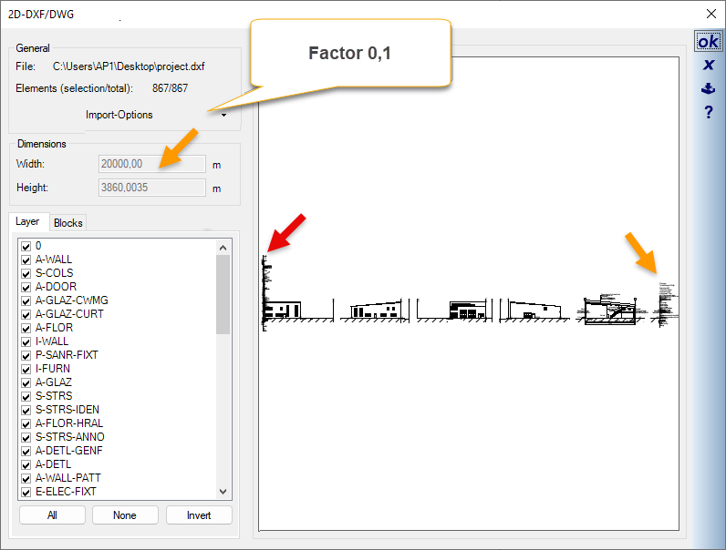
- Factor 0.1: The display improves, but fonts often still stack up into “towers”. The dimension for the width is still listed as 20,000 m (is the maximum value that can be represented)
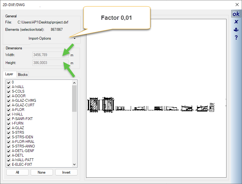
- Factor 0.01 (or smaller): The drawing is displayed correctly. The font towers disappear, and the dimensions for width and height of the drawing are below 20,000 m (the maximum value that can be displayed) and therefore within a realistic range.
Tip for checking: After importing, measure (short key d) a known dimension in the drawing. If the dimension measured in cadvilla matches the labeled dimension of the drawing, you have chosen the correct factor.
