


Do you need to create a precise wall foundation detail for your architectural floor plan? In this comprehensive tutorial, we will show you exactly how to draft a professional construction detail using the intelligent 2D drawing tools in cadvilla. First, we will explain how to properly set up your workspace with the correct scale and precise guidelines. Furthermore, you will learn how to apply exact patterns to various materials, duplicate brick objects efficiently, and add professional dimensions. Ultimately, we will demonstrate how to save your completed detail as a 2D symbol so that you can easily insert it into any future projects.
Please note: The zoom functions demonstrated in the video are only valid up to version 5. In newer versions, you can zoom simply by scrolling the mouse wheel. For further details, please refer to our post on zooming in the 2D and 3D view.
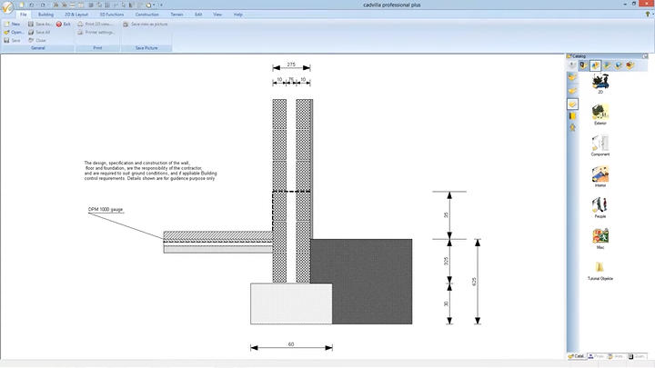
Here is a summarized breakdown of the basic workflow:
1. Preparation and Adjusting the Scale
[01:12] Change the Project Scale
- First of all, deactivate the grid to ensure you can snap to points much more easily.

- Change the project’s overall scale, if necessary (in our example, we change it from 1:50 to 1:10).
- To do this, perform a
right-clickanywhere in the 2D view and selectProperties. - Consequently, a window will pop up where you can select your desired value under the
Scaledropdown menu. Confirm withOK.
[02:04] Hide Interfering Elements (north arrow, origin)
- To maintain a better overview of your drawing space, you should deactivate the origin point and the north arrow.
- Therefore,
right-clickinto the view and selectVisibility. - Next, open the
Help elementssection, deselect the checkboxes forOriginandNorth arrow, and finish the process by clickingOK.
2. Construction with Guidelines and Rectangles
[02:59] Setting Guidelines
- For the exact input of a wall foundation detail, we highly recommend using guidelines as a base reference.
- Go to the top menu and select
2D layout>2D guidelines>Guideline>Horizontal guideline(orVertical guideline). - Tip: You can change the line color (e.g., to green) by making a
right-clickon the guideline >Properties>Appearance>Color. - Initially, place one horizontal and one vertical guideline at any position to serve as a reference point for the subsequent lines.
- Afterwards, press the shortcut
pto easily activate thenumeric parallel guidelinefunction. This allows you to build a precise grid for your detail by typing in the exact distance.
[06:03] Draw the Foundation Base
- In order to define the concrete foundation base, you can simply use a rectangle function. Select
2D layout>Rectangle>Rectangle. - Place the corner points exactly at the intersections of your green guidelines. Once you are finished, press
ESC.
[06:37] Adjusting Fill and Pattern (Hatch)
- Select the rectangle you just drew, perform a
right-click, and confidently chooseProperties(or double left-click the element). - Now, navigate to the
Fillingsection and selectPatternas your type. - Note: You can find various materials via the path
Graphics2D>2D_Pattern>Hatches. Here you will find standard hatches for reinforced concrete, insulation, gravel, plaster, and much more. Please note that using 2D patterns is exclusively available from cadvilla professional upwards.
3. Complex Shapes and Copying Objects
[12:13] Create Multiple Copies of Objects
- In order to copy an object like a brick multiple times across your wall layer, start by selecting it.
- Next,
right-clickthe block and chooseMultiple copy. - Within the
Tool optionswindow, you can define the preciseNumber, theDistance, and theDirection(e.g., Top 90°) of your copies. Make sure to selectClear distanceso the spacing calculates perfectly between the elements, and finally confirm withOK.
[16:47] optional: Polygons and Rectangles for Complex Layers
- To draw complex ground layers or custom shapes, you can either use multiple rectangles or a closed polygon (via
2D layout>Polygon>Closed polygon). - If you use a polygon, simply click the corner points one by one. To finish the shape, press the
right mouse buttonand selectComplete input, then pressESC. - Furthermore, you can change the filling and pattern of a polygon in the exact same way as you did with the rectangle via the
Propertiesmenu.
[17:09] Move Objects to the Front or Back
- Sometimes, you might need to adjust the overlapping order of your elements. If you want to move an object to the foreground or background, simply select it first.
- Then, perform a
right-clickand selectSend to back(orBring to front/One layer backwards) from the context menu.
[18:50] Input of Further 2D Elements
- From this point on in the video, you will see the systematic input of further 2D blocks and rectangles utilizing various fill colors and custom patterns for the different building materials.
4. Adding Dimensions and Labeling
To complete the detail drawing, it must be properly labeled and dimensioned so that it is readable on the building site.
- [21:18] Dimensioning: Navigate to
2D layout>Dimensions. To quickly define the style, make aright-clickto open theProperties. Here, you can easily edit the appearance, measurement units, and text properties, as well as set the style for your dimension arrows (e.g.,Arrow filled). - [22:56] Texts / Labels: Add standard descriptive texts by choosing
2D layout>Text>Labeling. Place the text field with a left-click, type in your description, and adjust the font size before clickingOK. - [24:00] Item Texts (Position Texts): Go to
2D layout>Text>Item text. Click on the specific 2D object you want to annotate (e.g., the DPM rectangle layer), place the leader line, and easily edit the descriptive text inside the properties menu.
5. Save the Detail as a Symbol and Insert It
[26:10] Save Detail as a 2D Symbol File
- Select your entire, fully finished wall foundation detail by dragging a large selection box around it.
- Afterwards,
right-clickanywhere inside the selected area and chooseSave selected objects as 2D Symbol. - Type a suitable name for the file (e.g., “Wall foundation detail”) and press
OK. Your custom detail is now securely saved in your personal library.
[27:00] Insert the 2D Graphic into a Project
- To effortlessly insert this 2D graphic into a completely different project (like a cross-section or your main floor plan), open the right-side
Catalog. - Navigate to
2D Symbols>Graphics 2D(or your chosen save location). - Select your saved wall foundation detail, press
OK, and intuitively position it at the desired location within your model home.
Tip: Use Existing Project Data for Details
You can also use existing sections of your 3D project to create a wall foundation detail, which saves significant time and effort.
- Define a Section: First, generate a standard section view at the desired location in your 3D project.
- Convert into 2D Graphic: Now, convert this active section view into a pure, flat 2D graphic. To achieve this, simply click on
View>New 2D-Graphic-Viewin the top menu. - Edit the Detail: Consequently, you can freely modify this new 2D graphic view without affecting your 3D model. Just add new materials, remove unwanted lines, and adjust the detail using standard 2D drawing tools, exactly as demonstrated in this video.