

Do you want to create a standard-compliant fire escape and rescue plan for your building? With the special add-on module in cadvilla professional plus, this is possible quickly and easily. You can work on the basis of your existing floor plan and transform it into a clear fire escape plan with just a few clicks. Simply add important symbols, colored escape routes, and legends via drag-and-drop. In this tutorial, we will show you step by step how to use the wizard and finish your plan professionally.
The add-on module Fire Escape Plan Wizard can also be purchased as a separate plugin for your cadvilla version.

1. Preparation and starting the wizard
[00:22] Load project
- First, open your existing cadvilla project for which the fire escape plan is to be created.
[01:09] Set up printer and paper format
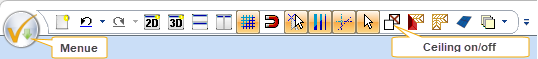
- Open the
menueand selectPrinter settings...
- In the Print window, click on
Properties...and then on theMore...(or Advanced) tab. - Set the
Papersizeto the desired format (e.g.,A3) and confirm all windows withOK.
[02:06] Call up the fire escape plan wizard
- Switch to the
2D & Layouttab and click on theWizardfunction. - The window for the import settings opens.
[02:17] Adjust settings in the wizard
- Choose the
languageof your choice. - Select the option
Use settings of the active 2D view. - If necessary, adjust the
Scale(e.g., to1:125) and confirm with theTABkey. The preview updates automatically. - Under
Paper, check whether the size is correctly set to A3. - Use the arrow buttons under
Frame positionto optimally align the floor plan on the sheet. You can adjust theStep width(e.g., to3.00 m) to move the frame faster. - Under the
Wallsection, you can define the 2D display, the fill style, and the fill color of the walls of the floor plan in the fire escape plan. - Finally, click on
Finish. The floor plan for the fire escape plan is now generated.
2. Draw guidelines and escape routes
[05:14] Introduction to the escape route concept
[06:15] Set guidelines for precise working
- Select
2D & Layout>2D guidelines>Guideline>Centred guideline(orFree guideline). - Draw guidelines (e.g., centrally through the corridor or in the stair area) in order to be able to place the arrows exactly later.
- Tip: Hold down
Ctrl + Wto align the line exactly horizontally or vertically. PressEscto end the function.
[07:33] Place location and escape arrows (drawing elements)
- Go to the
2D & Layouttab >Drawing elementsand selectSet location. - Right-click to open the properties, select
Propertiesand set theDiameter(e.g., to1.00 m). Place the location symbol in the desired room. - Now select the first arrow under
2D & Layout>Drawing elements>Arrow, angled(orArrow, straight) to draw the escape route. - Here too, adjust the
Widthof the arrows via right-click >Properties(e.g.,0.30 m) and click along the escape route along your guidelines. - Complete the fire escape plan with the other escape arrows.
3. Color rooms and place symbols
[11:01] Highlight escape routes in color (room representation)
- Select the
Room 2D representationfunction in the menu. - Click
Colorand choose a light green (e.g.,LightGreen) - Click on
Colour a roomand select the corridors and rooms that form the escape route. - These are now automatically colored green.
[12:47] Insert fire protection and rescue signs
- Open the
Catalogon the right side and navigate to2D Symbols>Fire escape plans. - Under
Fire safety signs, select e.g. the fire extinguisher and place it in the plan with the left mouse button held down. - To adjust the size, select the symbol, right-click >
Propertiesand change theWidth(e.g., to0.80 m). Make sure thatMaintain aspect ratiois activated. - Use the functions
Move with reference pointandCopy with reference pointto align the symbols exactly on the walls and duplicate them. - Insert rescue signs (e.g., First aid or Evacuation assembly point) in the same way.
4. Add legends and labels
[17:48] Insert symbol legend
- Click on
2D & Layout>Legendsin the menu and select2D Symbol legend. - The legend is now attached to the mouse pointer. The dialog window shows which symbols are used in the plan.
- Place the legend with a left-click on the plan.
- Via the selection of the legend > right-click >
Properties, you can subsequently adjust theWidthof the legend.
[19:30] Place information texts (behavior in case of fire / emergency)
- Go to the catalog under
Action plates en-GB. - Drag and drop the text blocks for “Fire Action” and emergency conduct onto your plan and place them.
[20:38] Individual texts and labels
- Select
Text>Item text. - Click on your location symbol and select the text
Positionto insert it automatically. - Via selection of the text > right-click >
Properties, you can adjust the text color (e.g., blue). - Use the
Labelingfunction to insert further free texts (e.g., “Office Building Salzburg, 2. Floor”) and position them on the plan. You can also change the font size (e.g.,5.0 mm) and style.
[23:50] Conclusion
- Check all elements. Your fire escape and rescue plan is now finished and ready for printing.
Note: If no sheet frame is displayed after starting the wizard, it may be due to the selected printer under the printer setup. In this case, simply select a different printer. A suitable and at the same time free PDF printer would be, for example, 7-PDF (Community Edition, free of charge).