

Do you want to draw a simple garage with a flat roof or pent roof in cadvilla? In this tutorial, we show you step by step how to set the external walls, insert a garage door, and construct the roof. You will also learn how to add practical details such as a window and a wall cutout for ventilation. With the help of guidelines and the right settings, you will succeed with your planning in no time. Start your garage project now.
1. Create a guideline grid and define the rough height
[00:54] Set basic cross from guidelines
- In the first step, open a new 2D view via
New. - Deactivate the grid and the line width to be able to snap and orient yourself better.

- In the upper menu, go to
2D & Layout>2D guidelines>guideline. - First select
Vertical guidelineand place it. Then set aHorizontal guidelineto create a basic cross.
[01:25] Parallel guidelines for the garage dimensions
- Use the shortcut
P(Numeric parallel guideline) to determine the external dimensions of the garage. - Set further lines at the desired distances in this way (in the video, e.g., 2.95 m, 3.20 m, and 5.95 m).
[02:19] Adjust rough height
- In the project tree on the right side, right-click on the
Ground floorand selectProperties. - Set the
Rough heightto2.45 m. - It is mandatory to deactivate the
Create automatic ceilingoption and confirm withOK.
2. Draw external walls and insert garage door
[02:59] Draw walls
- In the menu, select
Building>Walls>External wall>Between two points chain. - Set the wall thickness in advance to
0.10 m(right-click in 2D view >Properties). - Draw the walls along the intersections of your guideline grid.
- Tip: Use the key combination
Ctrl + Wto change the reference point of the wall (inside, center, outside) while drawing. End the input withEsc.
[04:55] Place garage door
- Select
Building>Door>Door>Free positioning. - Open the
Propertieswith a right-click and select a suitable garage door underSelection(e.g., Garage 1_250x215). - To place the door exactly in the middle of the wall, press the shortcut
M(Centre point) and click on the two inner corner points of the front wall.
[06:22] Adjust the display of the door
- Select the placed door, press the right mouse button, and open the
Propertiesagain. - Under
Top view, change theDisplay typetoWire frameto hide the opening angle. Also set theDepthof the opening to0.00 m.
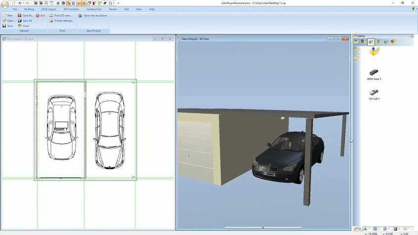
3. Optional: Flat roof (ceiling slab) and supports
[07:31] Enter flat roof via ceiling slab
- Use the shortcut
Pto set further guidelines for the covered forecourt of the garage. - Select
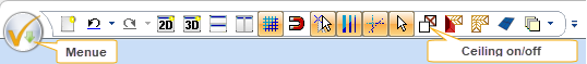
Building>Ceiling>Ceiling>Insert with rectangleand drag the slab over the desired corner points. - Press the Icon
Ceiling on/offto activate the view of the ceiling.
- Select the ceiling slab in the 3D view, open the
Propertiesvia the right mouse button and adjust theLevel(e.g.,2.35 m) as well as theHeight(0.10 m).
[09:27] Place supports for the flat roof
- Select
Building>Supports>Rectangular support>Free positioning. - Set
WidthandDepthto0.15 m. - Place the supports at the front corners of the flat roof. Here too, use
Ctrl + Wfor the appropriate insertion point.
4. Define and texture pent roof / sloping roof
[11:41] Preparation for the pent roof
- If you decide against the flat roof, select the previously created ceiling slab in the 3D view and delete it with the
Deletekey.
[11:55] Insert roof shape
- Switch to the 2D view and select
Building>Roof construction>Insert roof>Insert rectangular roof. - Drag the roof diagonally over the outer edges of the garage walls. The properties dialog will now open automatically.
[12:21] Set roof properties (pent roof)
- For roof sides 1, 2, and 4, change the
ProfiletoGableand set theOverhangto0.10 m. Confirm inputs with theTabkey. - For roof side 3, set the
ProfiletoHipped roof, thePitchto3.00 degrees, and theHeightto2.15 m. - Deactivate all checkboxes under the
Wood constructionpoint, as we only need a solid roof slab. - Under
Cladding, set theCladding thicknessto0.10 mand confirm withOK. - Select the support with a right-click >
Propertiesand change the height of the support so that it connects to the pent roof.
[16:29] Texture roof
- Activate a 3D view.
- Use the
3D functions>Transfer materialfunction to assign the roof a concrete look from the catalog, for example.
5. Insert window and wall cutout (ventilation)
[17:26] Insert window construction
- Select
Building>Window>Window construction>Free positioning. - Press the right mouse button in the 2D view and in the
Properties, set the opening dimensionsWidthandHeightto0.50 mand theSill heightto1.50 m. - Under
Top view, deactivate theShow prompt height textoption. - Place the window in the wall. Use
Ctrl + Wand use from theconstructural supportthePoint with distance fromfunction (shortcutA)to align it exactly.
[19:52] Define wall cutout (external ventilation)
- In the 2D view, select the wall in which the external ventilation should be created. Pay attention to the selected wall side (is displayed in red).
- Press the right mouse button and select
Create wall section. - Select
Building>Cutout>Wall Cutout>Rectangle. - Draw the cutout freely in the 2D section view by clicking two diagonal points.
- Confirm the input with
Esc. The ventilation is now visible in the 3D view.