


Do you want to create a realistic building plot with a slope or elevation for your architectural project? In this tutorial, you will learn step by step how to define a terrain gradient using cadvilla. First, we explain how to adjust the Environment layer and set up helpful guidelines. Afterward, we show you how to enter exact height contours to create slopes, ridges, and immersions. As a result, you will be able to visualize even complex outdoor areas accurately in 3D.
Please note: The zoom functions demonstrated in the video are only valid up to version 5. In newer versions, you can zoom simply by scrolling the mouse wheel. For further details, please refer to our post on zooming in the 2D and 3D view.
Below is a detailed overview of the video’s content.
1. Prepare and Adjust the Environment
[00:36] Activate the Environment Layer
- As a first step, deselect the grid and the line width in the 2D view. Therefore, you get a much better overview, and snapping to specific points becomes easier.

- Next, go to the
Projectspanel on the right side and select theEnvironmentlayer. - In order to see the terrain in both views, make sure
Environmentis also activated as the current element for the 2D view. By doing this, the terrain becomes fully editable.
[02:04] Important Warning for the Environment Frame
- When designing your terrain, you must keep an important rule in mind: “Please note that all terrain points and terrain lines have to be inside of this frame which displays our environment.”
- Consequently, always maintain a minimum distance of approximately 1 meter from the outer edges of the planning area.

[02:34] Modify the Dimensions of the Environment
- If your planned terrain gradient requires more space than the default environment provides, you can easily adjust its size.
- To do this, hold the
CTRLkey and click on theEnvironmentlayer in theProjectspanel to select it in the 2D view (indicated by a red outline). - Right-click and select
Properties. TheGeneral Areadialog box will appear. - Here, you can change dimensions such as
WidthandDepth. Once you are done, pressOKand hit theESC-key to deselect.

2. Set Guidelines and Define the Absolute Level
[03:51] Use Guidelines for Support
- To accurately define the outline of your slope, we highly recommend using guidelines.
- Navigate to
2D & Layout>2D guidelines>Guideline>Numeric parallel guideline(Alternatively, you can just press the shortcutP). - Tip: To make the guidelines stand out, right-click, select
Properties, go toAppearance, and change theColorto green. - Afterwards, enter specific distances (e.g.,
3meters) to create a structured grid for your different height levels.
[07:20] Adjust the Absolute Level
- Before entering the actual height contours, you might need to change the absolute level of your environment. This is especially true if your plot falls below the ground level.
- Right-click on
Environmentin theProjectspanel and selectProperties. - In the
Layer Generaldialog, look forAbsolute level. Here, enter the lowest point of your future terrain (in the video, this is-2.00meters). Confirm withOK. - Note: The absolute level in cadvilla is not the height above sea level. Instead, it refers specifically to the lowest point of the property relative to the zero-level of your floor plan (usually the bottom edge of the ground floor).
3. Enter and Define Height Contours
[07:55] Select the Height Contour Tool
- To start shaping the terrain, switch to the 2D view.
- Then navigate to
Terrain>Terrain contour>Enter height contour.
[08:23] Important Rule for Contour Lines
- At this point, a crucial warning must be observed: “Please note that two high contours never should cross each other. If they meet in edge points they MUST have the same worth.”
- If you ignore this rule, the 3D calculation of the terrain will fail.
[08:40] Draw and Complete Height Contours
- Click along the previously created guidelines to set the points for your contour line.
- Once you have placed the points for a specific contour line, right-click and select
Completefrom the context menu.
[08:57] Set the Exact Height Values
- After completing the line, the
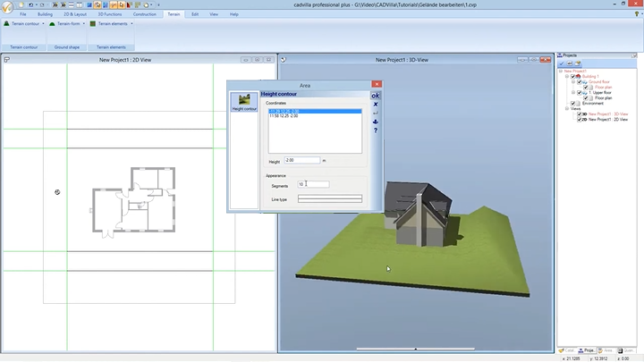
Area Height contourdialog window opens automatically. - In this window, you define the specific
Heightfor each individual point of the drawn line (for example,0.00meters for the ground level or-2.00for a lower slope). - Furthermore, we recommend setting the value for
Segmentsto3. This determines how smoothly the terrain transitions between points. Confirm your settings withOK. - Press the
ESC-key to deselect the current contour, and then proceed to enter the remaining height contours (e.g., the+2.00meter peak).
[12:20] Edit Height Contours Later
- If you ever need to change the values of a contour line later, simply select the desired contour in the 2D view.
- Right-click it and choose
Properties. The dialog will open again, allowing you to quickly adjust the heights or segments.
[13:10] Lateral Height Contours for Ridges and Immersions
- If you want to define a specific ridge or an immersion on the sides of your terrain surface, you should also define lateral height contours.
- Start again via
Terrain>Terrain contour>Enter height contourand draw lines along the side edges. - Set the exact heights for each point bridging the lowest and highest levels (e.g., starting at
-2.00, passing through0.00, and ending at2.00). - As a result, the terrain mesh connects correctly on all sides, giving you a clean and closed 3D slope.