

Welcome to our technical guide on fixing architectural inaccuracies in cadvilla. In this tutorial, you will learn how to recognize and correct slightly slanted walls that prevent closed rooms from generating correctly. Furthermore, we explain both the automatic repair function and the manual rotation method. Consequently, following these steps will ensure your floor plans maintain exact 90-degree angles and generate accurate spatial dimensions.
Please note: The zoom functions demonstrated in the video are only valid up to version 5. In newer versions, you can zoom simply by scrolling the mouse wheel. For further details, please refer to our post on zooming in the 2D and 3D view.
1. Recognizing Leaning Walls
Sometimes, walls are inadvertently drawn with minimal angle deviations (e.g., 0.1°). Consequently, these slanted walls cause visual “staircase effects” upon close zooming and prevent the software from defining closed room areas.
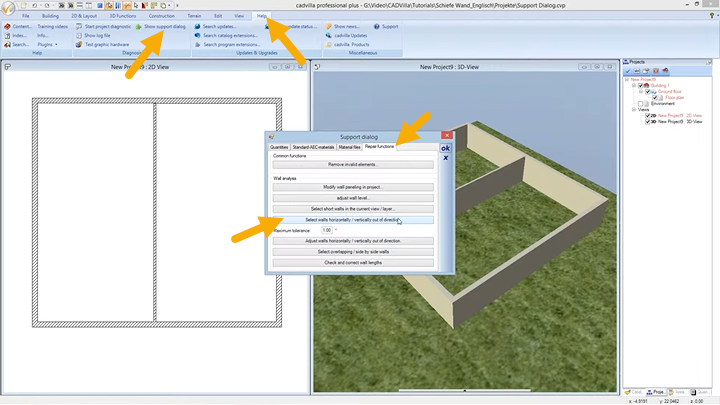
[1:40] Opening the Support Dialog
- First, navigate to the top menu and select
Help>Show support dialog. - Next, switch to the
Repair functionstab (also referred to as the Test page) inside the dialog window.
[2:19] Defining the Tolerance
- Under the settings, you can define a
Maximum tolerancevalue (for example, 0.5°). Therefore, any walls deviating from the strictly horizontal or vertical axis by less than this defined value will be identified as leaning.
[2:32] Selecting the Walls
- Subsequently, click the button labeled
Select walls horizontally / vertically out of direction. - As a result, the affected walls are highlighted in red in your 2D view. Additionally, a pop-up message will display the exact number of identified errors (e.g., “Test: 1 wall selected”).
2. Automatic Wall Correction
After successfully selecting the slanted walls, you can align them automatically using the built-in repair tool.
[2:58] Executing the Correction
- Inside the support dialog, click the explicitly named button
Adjust walls horizontally / vertically out of direction.
[3:07] Important Note for Automatic Wall Correction
- Please control the dimensions of the room after you have used the automatic wall correction function. Because the automated rotation slightly moves the wall’s endpoint, previous room dimensions and wall connections might shift and require manual verification.
- [3:15] How the function works: During this automated process, the wall rotates directly around its first input point. Consequently, the second point shifts to align exactly on the 0° or 90° axis.
3. Manual Correction (Rotating via Reference Point)
If you require full control over the exact point of rotation, the manual correction method is the required approach.
[4:08] Preparation
- Before you correct walls manually, please deactivate the line width and the grid. Therefore, you can be absolutely sure to catch the correct geometric reference point without interference.

[4:25] Selecting the Tool
- First, select the leaning wall directly in your 2D view.
- Next, navigate to
Edit>Rotate>around Z-axis with reference point.
[4:38] Setting the Reference Points
- Initially, click on the desired center of rotation (for example, the correct corner point connecting to the outer wall).
- Afterward, click on the opposite endpoint of the slanted wall.
[5:06] Aligning with the CTRL Key
- Now, move your mouse in the target direction while pressing and holding the
CTRLkey. - Consequently, this action activates the angular grid. This feature forces the wall geometry exclusively into defined angles (e.g., 0°, 15°, 30°, 90°). With this function, it is possible to insert 100% horizontal or vertical lines.
[5:37] Completing the Rotation
- Finally, confirm the exact horizontal or vertical alignment with a left mouse click. Afterward, press the
ESCkey to exit the rotation function.