Do you want to have full control over the ceiling constructions in your floor plans? In this tutorial, we will show you how to handle automatic and manual ceilings in the cadvilla® architecture software. You will learn how to control the visibility of ceilings in 2D and 3D views, adjust the depth of the ceiling support, and manually draw individual ceiling slabs for complex areas. With these steps, you will master both quick standard inputs and customized constructions for your project.
General information about ceilings in cadvilla®
- Visibility: By default, floor ceilings entered in cadvilla are not displayed in 2D top views and 3D views. In the 2D view, this serves to provide a better overview of the floor plan. In the 3D view, it allows a direct look from above into the rooms (“view from the inside”).
- Areas of application:
- Automatic ceilings: Ideal for quick and standardized inputs, as they automatically adapt to the external walls.
- Manual ceilings: Perfect for individual constructions such as balconies, projections, or complex areas that cannot be covered by the automatic function.
1. Activate the visibility of the ceilings
[00:49] Display ceilings in the 3D view
- Switch to your 3D view.
- Right-click in the view and select
Visibility.... - Open the
Construction Elementssection and check the box forCeilings. The ceiling is now displayed in the 3D model. - Tip: Alternatively, you can also quickly control the visibility of the ceiling via the
Ceiling on/officon in the upper toolbar.

[01:36] Display ceilings in the 2D view
- Switch to your 2D top view.
- Right-click here as well and select
Visibility.... - Under
Construction Elements, activate the itemCeiling. The ceiling contour is now visible in the floor plan. - Tip: Also here, you can change the visibility of the ceiling via the
Ceiling on/officon in the upper toolbar.
2. Change the support of the automatic ceiling
[02:21] Adjust ceiling support for a single wall
- Select an external wall in the floor plan, right-click, and select
Properties.... - In the dialog window, you will find the
Ceiling supportsection. - Change the value for the
Depthhere (e.g., from the standard 0.15 m to 0.365 m to match it exactly to the wall thickness). - Confirm with
OKand pressESC. In the 3D view, you will now see that the ceiling is flush with the outer edge of the wall.
[03:38] Transfer properties to other walls
- To achieve a uniform result, you can apply this change to all walls.
- Select the changed wall, right-click, and select
Transfer properties. - Select the option for the ceiling support depth and transfer the properties to all walls in the layer.
3. Create manual ceilings (e.g., for balconies)
[04:45] Deactivate automatic ceiling when creating a new floor
- When you create a new floor (in the project tree, right-click on
Building 1>New floor above), the automatic ceiling is activated by default. - To draw a ceiling completely manually, uncheck the
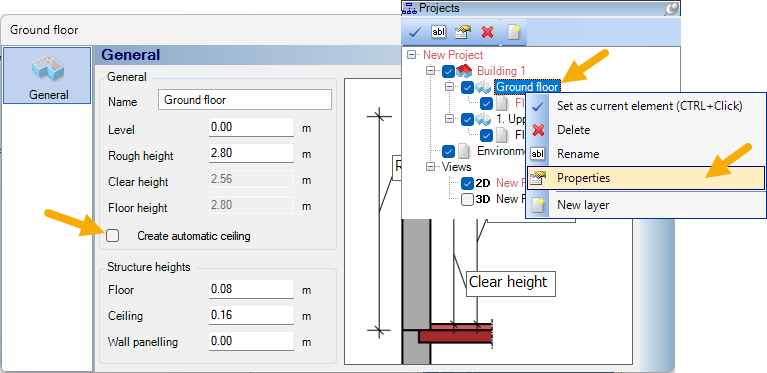
Create automatic ceilingbox in theGeneraltab of the floor dialog. - [07:04] Tip: You can also switch off the automatic function later for an already existing floor in order to draw a manual ceiling afterwards.
- To do this, hold down the
CTRLkey and click on the corresponding floor (e.g.,Ground floor) in the project window to select it. - Right-click and select
Properties.... - In the
Generaltab, deactivate theCreate automatic ceilingoption.
- To do this, hold down the
[05:30] Preparation for the manual ceiling
- In the video, you now see the newly created floor without a ceiling. The look into the 3D view shows the open building from above.
- For the exact input of the manual ceiling, green guidelines have already been set in the 2D floor plan, which mark the exact course (e.g., over a bay window or projection).
- Deactivate the grid (
Grid on/off) and the line width (Line width on/off) to be able to snap and orient yourself better.
[05:54] Call up the “Insert with polygon” function
- Click in the 2D view to activate it.
- Switch to the
Buildingtab in the upper ribbon. - Click on the
Ceiling>Ceiling>Insert with polygon.
[06:07] Draw polygon for the ceiling
- Now snap the first corner point of your planned ceiling in the 2D floor plan (e.g., at the top left corner of the marked area) and click with the left mouse button.
- Move the mouse to the next corner point along the guidelines and click again.
- Continue in this way and click all further corner points (third and fourth point) of the desired ceiling area. The program automatically draws a contour line along with it.
[06:28] Complete the input of the ceiling slab
- When you have set the last point before closing the polygon, right-click.
- In the context menu that appears, select the item
Complete with <Enter>. - Press the
ESCkey to end the function. - The completed, gray ceiling slab now immediately appears in the 3D view.
[06:48] Check the result in the 3D view
- Click in the 3D view and rotate the model while holding down the mouse button.
- You can now wonderfully see how the manually drawn ceiling exactly covers the desired area (including the projection) – a shape that would not have been possible with the pure automatic ceiling.
4. Create a manual ceiling with the support of guidelines
[07:57] Set centered guidelines in the walls for manual input
- Use guidelines for precise construction. Select
2D & Layout>2D Guidelines>Guideline(e.g.,Centered guidelineor parallel lines). - Place the lines at the points where the edges of your new ceiling should run. Tip: Hold down the
CTRLkey to align lines exactly horizontally or vertically.
[09:02] Draw ceiling slab manually
- In the
Buildingmenu, select the itemCeiling>Ceiling>Insert with polygon. - Now click the corner points of your new ceiling one after the other along the guidelines (e.g., to include a balcony projection).
- When you have set all points, right-click and select
Complete with <Enter>. PressESC. - Check your result in the 3D view. You have now successfully created an individual ceiling slab.
Tip:
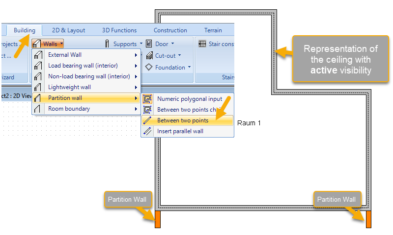
In the case of protruding walls, the outline of a building can sometimes not be found automatically. This influences or prevents the formation of the automatic ceiling. Therefore, generally enter protruding outline walls as partition walls (shown here in orange for better distinction).