


Have you acquired an existing property and want to comprehensively renovate or rebuild the project? In this guide, we show you in detail how to proceed most efficiently with a partial demolition and subsequent renovation measures in the cadvilla house planning software. Step by step, you will learn how to create the necessary layer structures, place elements correctly, and subsequently color-code the components for demolition or new construction. Consequently, through this structured approach, you will maintain an overview of your renovation project at all times and create clean, professional building plans for authorities or craftsmen.
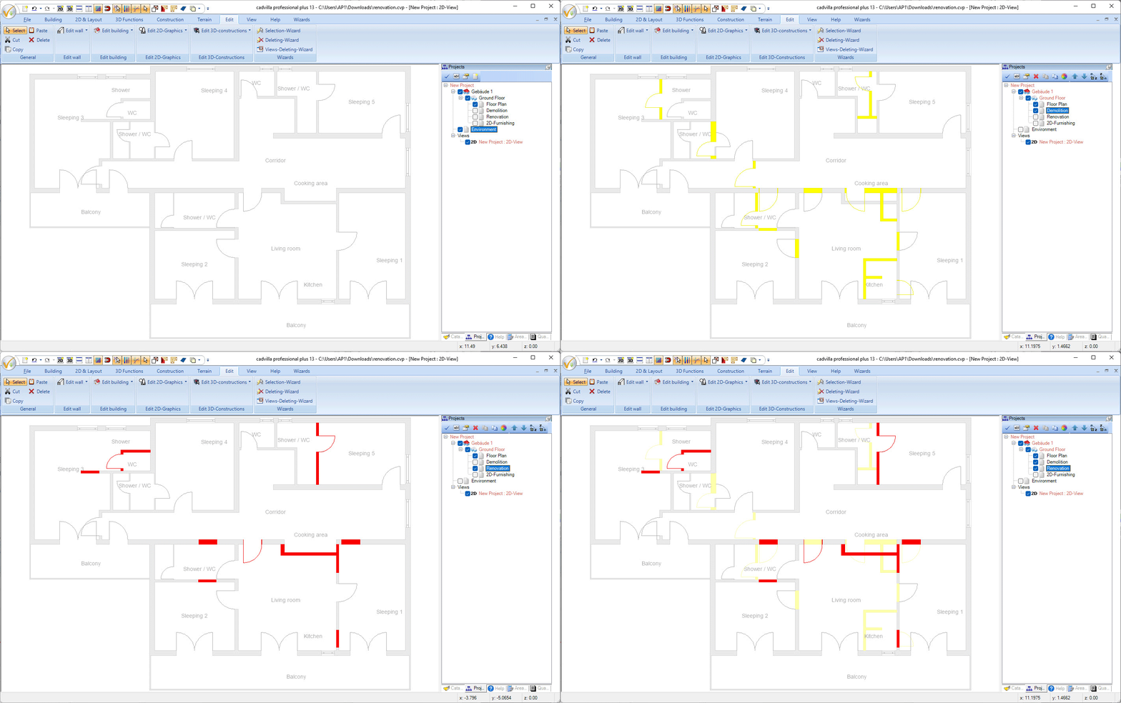
Note: Please note that some functions mentioned here are only available from version 12 onwards.
General information on drawing renovation projects
- Important: A building plan for a renovation always relies on the final desired state. Therefore, you first draw the project exactly as it should look finally after completion. Here, the finished floor plan of the respective floor must always be located on the standard layer Floor plan.
- Attention: Absolutely avoid copying entire floors into a demolition or renovation layer. Instead, always transfer only individual wall segments together with the windows and doors possibly contained therein.
- Furthermore, the walls drawn on the demolition and renovation layer must never form closed rooms, as this would disrupt the room evaluation of the software.
1. Create layers and establish structure
Create additional layers for the construction phases
- In the first step, create two additional layers for each floor in your project to clearly separate the construction phases from each other later.
- The first new layer contains all elements for the partial demolition. Accordingly, name this layer
Demolition, for example. - In addition, generate a second layer for all new construction measures. Consequently, you name this layer
Renovation.
Draw elements for the demolition
- Now, switch to the
Demolitionlayer. Then, draw exactly all components here that are to be removed in reality. - Tip: Note that doors and windows in cadvilla can principally only be positioned within a wall. Therefore, when drawing a door to be demolished on the
Demolitionlayer, for example, you must first place a short wall piece and only afterwards insert the door into this section.
2. Transfer newly planned elements to the renovation layer
Copy and paste elements
- Next, switch to the Renovation layer to represent all newly added elements.
- Tip: Since these new components ideally already exist on your final floor plan layer, you can significantly ease the drawing work. Simply select the new elements in the floor plan layer, copy them to the clipboard via the keyboard shortcut
CTRL+C, and subsequently paste them accurately into the Renovation layer usingCTRL+V.
Adjust wall lengths subsequently
- Should a wall inserted on the Renovation layer be too long – for example, because only a part of the wall is newly built – you must shorten it accordingly.
- To do this, select the path
Edit>Edit walls>Extend / Shorten wallin the upper menu bar, or alternatively use the shortcut keyVto precisely adapt the wall segments to the exact dimensions.
3. Color walls, windows, and doors according to standards
Coloring for the partial demolition (Yellow)
- So that the building plan ultimately remains clear, the elements must be color-marked according to the building drawing standards. For this, right-click on the Demolition layer in the project viewer on the right side and choose the menu item Set as current element.
- Afterwards, right-click on the Demolition layer again and call up the dialog
Change 2D representation / colours.

- In the subsequently appearing dialog window, change the color for the line properties and for the fillings to the color Yellow (standard color for demolition).
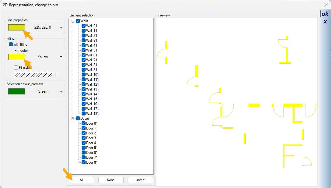
- Subsequently, select all respective components and confirm your selection with
OK.
Coloring for the renovation (Red)
- Finally, strictly perform the same process again for the
Renovationlayer. - However, in this editing step, set the color for the line properties as well as the fillings to Red (standard color for components to be newly built) and confirm again with
OK.
4. Prepare project for printing
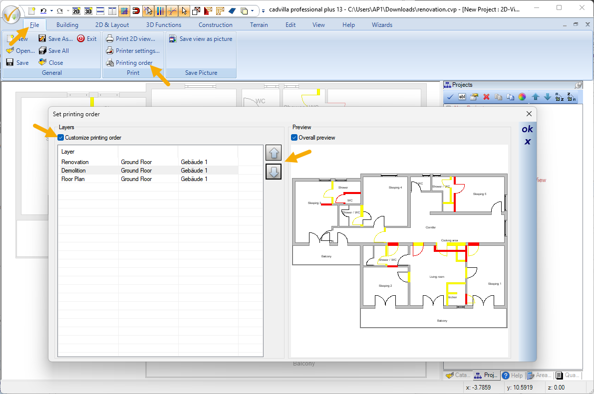
- In a special case, it can occur that individual layers must be arranged differently for the printout.
- To adjust the print sequence of the individual layers for the printout, click on
File>Print sequence. - Select Adjust
print sequence individuallyand move the individual layers in the layer stack as desired.
Attachment: Project file for the renovation project shown above