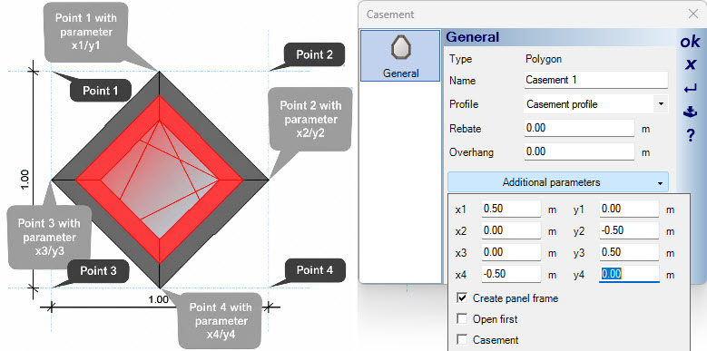
Are you currently planning a building in cadvilla with highly individual window shapes, such as sloped windows directly under the roof? Consequently, utilizing the window construction extension module, you can design not only standard windows but also complex polygonal casements exactly according to your architectural specifications. The technical input of such an asymmetrical casement is achieved simply through the targeted numerical adjustment of the individual corner point coordinates. Therefore, in this short tutorial, we will systematically show you how to accurately define a specific window casement using the polygon function.
If you technically require a casement in your window constructions that is not exactly rectangular (for example, intended for a sloped gable window), you can specifically define the desired shape via a polygon. Physically, this is done through the subsequent numerical adjustment of the corner points belonging to a standard casement.
Proceed exactly as follows to systematically achieve this:
1. Create the base casement as a rectangle
- Initially, start with the structural definition of the casement directly within your active window construction. Therefore, click on
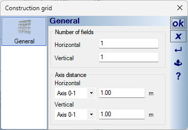
Construction>New construction>New window construction - Select the construction grid, press the right mouse button, and select Properties. In the subsequent dialog window, enter the value 1 for the vertical and horizontal fields respectively.
- To create a base casement, use the specific function located under
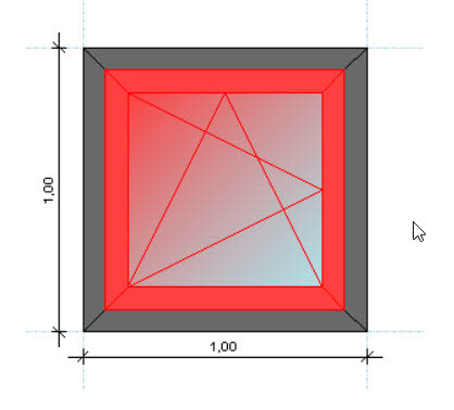
Construction>Casement>Polygon. - Draw a basic rectangle over the active snap points of the construction grid.
2. Call up the properties of the casement
- As soon as the rectangular casement is successfully created, select it actively with a single left mouse click.
- Subsequently, click exactly with the right mouse button on the marked casement.
- In the appearing context menu, securely select the item
Properties.
3. Adjust corner points via X/Y values
- Click on the
Additional parametersbutton inside the new dialog window. - Here, you will find the technical option to adjust the X and Y values for the 4 corner points of the casement individually.
- Now, carefully enter the desired metric coordinates to systematically shift the corner points.
Application example: As technically illustrated in the figures below, you can effectively form a window that is sloped on one or both sides just by altering the specific X and Y values from a basic rectangle. Finally, confirm your inputs securely, and the casement immediately adopts the newly defined polygon shape entirely.
Tip: For highly complex geometric shapes, briefly sketch the desired X and Y distances beforehand on a piece of paper in order to enter the numerical values inside the dialog window swiftly and flawlessly.