


Are you looking for the fastest way to accurately draw external walls in your architectural projects? In this simple step-by-step tutorial, you will learn how to master the numeric polygonal input tool in cadvilla (available from version 10). First, we will show you how to correctly set up your workspace and construct highly precise guidelines. Furthermore, we will explain how you can effortlessly adjust wall dimensions, define complex layer constructions, and automatically label floor areas. Finally, you will also discover how to easily apply textures and colors to your finished 3D walls.
Entering a building contour using the numeric polygonal input (starting from version 10) is, alongside entering via grid guidelines, one of the fastest ways to capture the exact external walls of a floor plan true to scale.
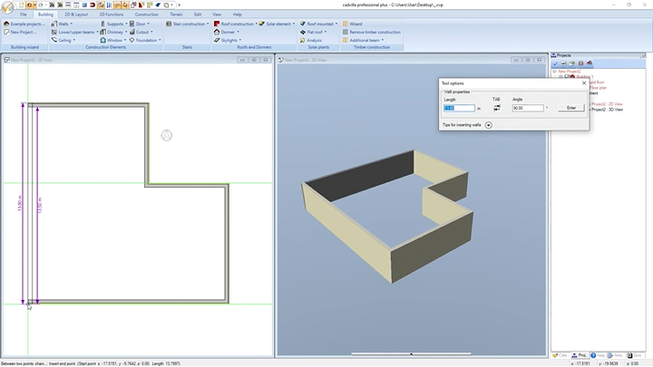
Below is a rough overview of the video’s content.
1. Inputting the External Walls
[00:23] Preparation of the Workspace
- Open both a
2D Viewand a3D Viewand place them side-by-side to ensure a better overview of your project. - Deactivate the
Gridand theLine widthin the top toolbar [01:17]. As a result, this simplifies the visual representation and ensures that your cursor always snaps precisely to the exact point you truly need.

[01:49] Creating Guidelines
- For better orientation, insert a
Vertical guideline(shortcutG) and aHorizontal guideline(shortcutH). This significantly makes the following input easier. Use the intersection of these two guidelines as the starting reference point for your floor plan. - Optional: Check and adjust the color of the guidelines (e.g., to Green) by pressing the
right mouse buttonand selectingProperties>Appearance[02:14]. - Optional: Save these specific guideline settings for all your future projects by clicking the
Save as defaultbutton [02:26].

[03:25] Starting the Numeric Polygonal Input
- To input external walls, navigate to the menu and select
Building>Walls>External wall>Numeric polygonal input. - Define the wall thickness (e.g.,
0.30m) via the properties dialog by pressing theright mouse buttonin the 2D view and selectingProperties. - Start entering your first wall point exactly at the intersection of the previously placed guidelines. If needed, change the reference point of the wall edge (axis, outside, inside) by repeatedly pressing the key combination
CTRL + W[04:19].
[04:31] Entering Wall Lengths and Angles
- After setting the second wall point with a left mouse click, the
Tool optionswindow automatically opens. Here, you can numerically modify the captured wall length (e.g.,13.80m). Confirm your input by pressingENTER[04:51]. - Please note that in addition to the wall length, the angle for the newly entered wall is also requested. This angle always refers permanently to the extension of the previous wall and the new wall to be drawn (relative angle). To quickly switch into the input field for the angle, simply use the
TABkey [05:23]. - TIP: For precise horizontal or vertical walls, purposefully hold down the
CTRLkey during your input. Consequently, the angle simply jumps within the predefined angular grid (e.g., 0°, 15°, 30°, 45°, 60°, 75°, 90°, …) [05:06]. Therefore, any deviation from 0° or 90° becomes immediately visually apparent to you while drawing.

[06:57] Finishing the External Wall Input
- Once you have entered all your walls, end the function by pressing the
ESCkey multiple times. Switch over to the 3D view to thoroughly check the finished floor plan (use thePos 1orHomekey to center everything on your screen) [07:05].
[07:19] Displaying the Floor Area
- Have the floor area of the new room displayed directly in the 2D view:
Right-clickon the room, selectProperties, and under theLabellingtab, check the box forFloor area. In the adjacent field, you can type a prefix like “FA=”.
2. Entering the Layer Construction of the Walls
IMPORTANT: Defining a wall with individual wall layers serves a purely graphical purpose and is not evaluated any further. Therefore, it is highly sensible to only include layers in your definition that remain clearly visible in a 1:50 scale representation. Extremely thin layers of just a few centimeters (e.g., a 1cm plaster layer) will merely appear as a thick black line when printing a 2D top view at a 1:50 scale, which ultimately just impairs the overall clarity.
However, to still maintain the correct overall wall thickness internally, simply add the thin layers to the existing main structural layers. Example: If the specified total wall thickness is 38cm (1cm plaster, 24cm brick, 12cm insulation, 1cm plaster) – simply define the purely graphical layer construction as 25cm brick and 13cm insulation material.
For a highly detailed representation of the layer construction including ALL layers, we strongly recommend creating a separate detail drawing (e.g., at a 1:20 scale) which can be additionally positioned on your plan.
[08:55] Defining the Layer Construction for Multi-Layer Walls
- To input external walls, navigate to the menu and select
Building>Walls>External wall>Numeric polygonal input. - In the 2D view, press the
right mouse button>Propertiesand switch over to theLayer constructiontab. - Click on
Insert new layer below selected layeror above to adjust your entire structure [09:56]. For example, create a wall consisting of an insulation layer (thickness:0.06m) and a concrete layer (thickness:0.24m). - Define the materials and colors of the layers by clicking on the
Materialbutton >2D Display(for example, choose the fill styleMonochromeYellow for the insulation andMonochromeGrey for the concrete) [11:18].
3. Changing the Entered Length of an Existing Wall
During the input of your floor plan, you always have 2 different options available to change existing wall lengths.
[14:11] Numeric Correction
- To numerically correct an existing wall, select the wall with a simple left mouse click. Afterwards, click on the
±icon (plus/minus symbol). - For the
Wall length, perfectly type in your newly desired measurement (e.g.,8.30m). Confirm everything withOK.
[15:21] Graphical Change (Extend / Shorten Wall)
- Alternatively, perform a graphical change of the wall length using the shortcut
V(Extend / shorten wall). - First, set up a guideline as your new target destination (e.g., using the shortcut
Pfor aNumeric parallel guidelineexactly at a distance) [15:03]. - Press
V, click directly on the wall you intend to extend, and subsequently click onto the newly drawn target guideline. The wall will instantly be extended exactly up to that specific line. - Optional: Double-check the wall length afterwards by using the shortcut
DforDistancemeasurement [15:38].
4. Coloring and Texturing an External Wall in the 3D View
Utilize various powerful tools to permanently change existing walls regarding their color and wall pattern.
Coloring an External Wall with a New Texture
- Open a new 3D view or switch to an existing 3D representation.
- Left-click on
Catalog>Texturesand freely choose any texture you desire. - While constantly holding down the left mouse button, directly drag the texture or color from the catalog onto the desired wall inside your 3D view. By default, the software intelligently applies this texture to all connected continuous external walls.
Texturing a Single Wall Only
- In order to texture merely a single wall (and strictly not the entire connected building), precisely drag your material from the catalog onto the wall and additionally hold down the
CTRLkey before you finally release the left mouse button.