

Are you looking to personalize your architectural drawings with unique styles? In this tutorial, we will show you exactly how to create your own custom 2D hatch patterns to fill 2D surfaces in cadvilla. First, you will learn how to set up a precise guideline grid to draw your pattern seamlessly. Afterward, we will explain how to save this pattern as a symbol file and apply it directly to your walls. Consequently, you will have full control over the visual representation of your floor plans, including adjustments to dimensions, line width, and rotation.
Please note: Some of the features shown are only available in the “cadvilla professional” and “cadvilla professional plus” versions. The zoom functions demonstrated in the video are only valid up to version 5. In newer versions, you can zoom simply by scrolling the mouse wheel. For further details, please refer to our post on zooming in the 2D and 3D view.
Below is a detailed overview of the video’s content.
1. Preparation: Creating a Guideline Grid
[01:03] Preparing the Workspace
- First, open a new project.
- To achieve a better overview and improve snapping, you should deactivate visual aids in the top toolbar. Click on
View>Grid on/offto deactivate the grid, and then selectView>Line width on/offto deactivate the line width.

- Tip: Press the
Home(orPos 1) key to execute theShow Allfunction and maximize your 2D view.
[01:29] Inserting Horizontal and Vertical Guidelines
- Next, create a grid as a drawing aid. Navigate to
2D Layout>2D guidelines>Guideline>Horizontal guideline. - Place the first line in your drawing area. After that, use the shortcut
P(which stands forNumeric parallel guideline) to create additional lines at a defined distance (e.g.,0.30m). - Repeat this exact process for the vertical guidelines by selecting
2D Layout>2D guidelines>Guideline>Vertical guideline.
[04:20] Adding Centered Guidelines
- To refine your grid further and define intersections clearly, select
2D Layout>2D guidelines>Guideline>Centered guideline. - Click on two opposite intersection points of your existing guideline grid to place the centered lines exactly in the middle.
2. Drawing and Saving the Hatch Pattern
[05:12] Drawing the 2D Pattern
- Now it is time to draw the actual pattern. Navigate to
2D Layout>Line>Between two points. - Draw your desired pattern (in the video, an “X” shape) along the guidelines. Important: You must ensure that your designed hatch pattern is seamlessly tileable in both the X and Y directions later on. Once finished, press
Escto exit the line drawing tool.
[06:24] Saving the Pattern as a 2D Symbol File
- Completely select your drawn pattern using a selection box (hold down the left mouse button and drag it over the object).
- Right-click on the selected lines and choose
Save selected objects as 2D Symbol.... - Save the file in the designated folder. The standard path is usually a directory in the cadvilla folder
..\Graphics2D\2D_Pattern\Hatches. Enter a name for the hatch pattern (e.g., “Test hatch”) and clickOK.
[07:55] Important Note About the Save Location
- Depending on your Windows User Account Control (UAC) settings, Windows might not save the 2D object directly in the program folder, but rather in a temporary virtual folder (e.g., C:\Users\’Username’\AppData\Local\VirtualStore\Program Files\cadvilla\Graphics2D). Therefore, please refer to our article on configuring Windows User Account Control if you cannot find your file.
3. Applying the Hatch Pattern to a Wall
[09:09] Drawing a Wall and Opening Properties
- To test the pattern, open a new project and select
Building>Wall>External wall>Between 2 points chain. - Before drawing, press the right mouse button on the wall and select
Properties.
[09:29] Assigning the Pattern as Material
- In the properties dialog, ensure the
Thicknessis set (e.g.,0.30m), then click onLayer construction. - Click on the
Materialdropdown and choose2D Display. - In this section, change the
Fill styleto2D Fill pattern. - Next, go to
2D Pattern from 2D Symboland click on thePathfield. - Browse for your previously saved symbol file (e.g., “Test hatch.cpa”), select it, and click
OKto apply it to the wall.
4. Modifying and Customizing the Hatch Pattern
Inside the 2D Display menu, you have numerous options to visually adjust how the pattern behaves within the wall component:
[10:15] Basic Settings and Hatching Function
- By default, the pattern’s
Dimensions(Width and Height) automatically adapt to the wall thickness (e.g.,0.30m). - Important: Generally, you should leave the
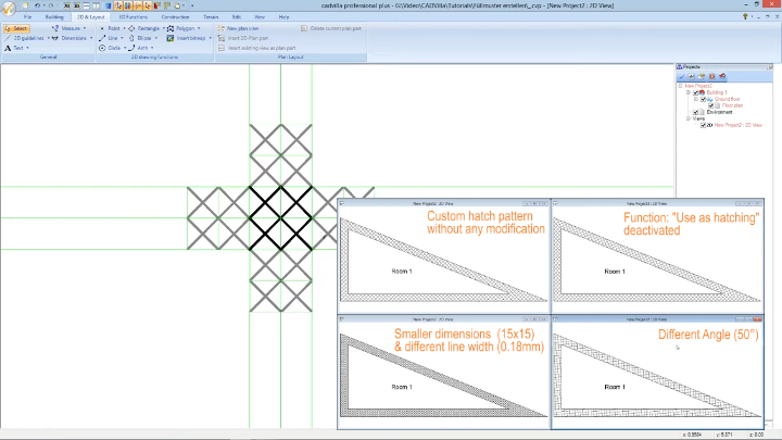
Use as hatchingcheckbox activated. - [12:40] If you specifically deactivate
Use as hatching, the pattern will be drawn continuously, meaning there will be no intersections or clean cut-offs at the wall edges (as demonstrated in the second view of the video).
[14:34] Modifying Dimensions and Line Width
- If you want a finer tile effect, you can change the values under
Dimensions. For instance, change theWidthto0.15m (the height will adjust automatically if “Maintain aspect ratio” is active). - To change the line thickness of your pattern, adjust the value under
Line width(e.g., to0.18mm).
[15:49] Rotating the Pattern
- Finally, if you wish to rotate the entire custom hatch pattern within the wall, simply enter a new value under
Angle(for example,50°). Confirm all your changes by clickingOK.