

Often, floor plans are only available as an image file (JPG, BMP, GIF, PNG) or as a scan. These files can be imported into cadvilla and used as a “blueprint” in the background to trace the floor plan with intelligent 3D components (walls, windows, doors).
Since image files do not contain information about the scale, the crucial step is correct scaling using a reference dimension. Note: You can find out how to proceed if you only have the floor plan in PDF format here.
Please note: The zoom functions demonstrated in the video are only valid up to version 5. In newer versions, you can zoom simply by scrolling the mouse wheel. For further details, please refer to our post on zooming in the 2D and 3D view.
Detailed process
1. Preparation of the view and layer: To structure the project cleanly, it is recommended to place the image on its own layer.
- Create a new 2D view.
- Right-click on the layer
Ground floorin the project manager and selectNew layer. - Name it, for example, “Ground floor – Picture” or “Sketch”.
2. Import image
- Select
2D & Layout>Insert bitmap>Rectanglefrom the menu. - Select the desired image file from your hard drive.
- Draw a rectangle in the 2D view where the image should appear, and end the function with
ESC.
3. Adjust scaling (most important step): So that the walls drawn later have the correct dimensions, the image must be brought to a 1:1 scale.
- Select the imported image.
- Right-click and select
Adjust scaling. - Now click on two points in the image whose distance is known to you (e.g., an external wall with a dimension chain). Tip: The longer the selected reference distance, the more accurate the result will be. The reference dimension should have a horizontal or vertical course.
- A window opens: Enter the actual length (
Target length) of this distance here and confirm withOK. - Control: To be on the safe side, measure another distance in the image using the function
2D & Layout>Measure>Distance(or shortcutD).
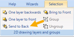
4. Move image to the background: So that the image does not block the view of your new walls while drawing:
- Select the image.
- Select the function
Send to Backin the selection menu at the top.
- Optional: Lock the layer with the image so as not to move it accidentally.
5. Enter walls and components
- Switch back to the
Floor planlayer for input. - Measure the wall thicknesses in the scaled image (key
D). - Select the wall tool (
Building>Walls), set the measured thickness in the properties, and trace the contours. - Use
CTRL+Wto change the reference point of the wall (left, right, center) during input.
Important notes on accuracy and further tips
Please note that capturing a floor plan via an image template can never be 100% dimensionally accurate for technical reasons. Even with very high-resolution images, minimal deviations at the click point (e.g., 1 to 2 screen pixels) quickly lead to inaccuracies of several centimeters on a 1:1 scale.
- Image resolution: An extremely high resolution of the scanned image does not necessarily improve accuracy, but it does strain performance. We therefore recommend a maximum image size of 150% of your screen resolution.
- Recommendation: Use the background image as a visual orientation, but ideally enter important dimensions (such as wall lengths or distances) manually via numeric input, provided they are known.
- Wall geometry: In cadvilla, every wall has a constant thickness from the start to the end point. Directly entering tapered walls (different wall thicknesses at the start and end) is therefore not possible.
- Image is not displayed (Only frame visible): If only an empty frame appears, select it, right-click to go to
Properties>Fillingand set the fill style toTexture. Also check there whether the path to the image file is still correct.

- Storage space: When the floor plan is finished, you can delete the layer with the image to reduce the file size of the project.
Video tutorial: Process and timestamps
This tutorial shows how to import a scanned plan or an image into cadvilla, scale it true to scale, and then use it as a template for tracing.
1. Preparation of the project
Before the image is imported, the working environment is optimized.
- [00:45] Start new project: An empty project is opened via
File>New. - [00:52] Maximize view: The 2D view window is maximized and the entire drawing area is centered with the
Pos 1(Home) key (Show all). - [01:17] Deactivate tools: To see the sketch better, the grid (
Grid on/off) and the line widths (Line width on/off) in the top menu are switched off.

- [01:35] Create own layer:
- Right-click on the layer
Ground floorin the project manager. - Select
New layer. - Name it
Ground floor - Pictureand confirm withOK. - Reason: This keeps the image separated from the walls drawn later.
- Right-click on the layer
2. Important notes before import
[02:20] Important information, how to prepare the sketch
- Scan quality: The plan must be scanned absolutely straight (at a 90° angle). Crooked scans should be corrected beforehand in an image editing program.
- Resolution: A maximum of 1.5 times the screen resolution is recommended to avoid performance problems.
- Accuracy: The procedure is never 100% exact. Over long distances (e.g., 20m), a few pixels of deviation in the image can lead to centimeter differences in the plan. Lens distortions in photos are also possible.
3. Import image
- [05:02] Import function: Select
2D & Layout>Insert bitmap>Rectanglefrom the menu. - [05:58] Select file: Select the image file (JPG, PNG, BMP). PDF files must be converted into an image format beforehand.
- [06:19] Place image: Draw a rectangle with two clicks (top left, bottom right) in which the image should appear. End with
ESC.
4. Adjust scaling (reference dimension)
The image does not yet have a scale. It must be calibrated using a known length in the plan.
- [06:53] Call function: Select the image, right-click and select
Adjust scaling. - [07:25] Select reference distance: Find the longest known dimension chain in the plan (in the video: 13.80 m). The longer the distance, the more accurate the result.
- [07:45] Set points:
- Zoom deep into the start point of the dimension chain (mouse wheel).
- Click the first point exactly.
- Hold down the
CTRLkey (for a horizontal line) and click the end point of the dimension chain.
- [08:34] Enter value: A window opens. Enter the actual dimension for
Target length(here:13.80) and confirm withOK.
5. Check scaling
- [08:55] Update view: Since the image size has changed, press
Pos 1orHome(Show all). - [09:27] Measure:
- Select
2D & Layout>Measure>Distance(or shortcut-keyD). - Measure the just scaled distance as a check (result in the video: 13.8093 m – a deviation of < 1 cm is acceptable for pixel images).
- To be on the safe side, also measure a vertical distance to rule out distortions.
- Select
6. Trace walls
Now the image is used as a base to create real 3D walls.
- [10:35] Determine wall thickness: Measure the thickness of an external wall in the image with the
Dkey (in the video approx. 0.29 m ⇾ is rounded to 0.30 m). - [12:03] Change layer: Activate the
Floor planlayer (no longer the picture layer!) so that the walls land there. - [12:19] Draw wall:
- Select
Building>Walls>External wall>Between two points chain. - Set the wall thickness. The dimension comes from the previous measurement.
- Set the starting point at a corner.
- Press
CTRL+Wto change the reference point of the wall so that the wall lies on the correct side of the line (e.g., outer edge).
- Select
- [14:09] Trace contour: Trace the outer contour of the building. Hold down the
CTRLkey to draw the walls exactly at right angles. - [16:35] Corrections: If walls do not close exactly (offset), use the function
Edit>Edit wall>Extend / shorten wall(shortcutV) to connect the corners cleanly.
7. Conclusion
- [18:13] Interior fitting: After the external walls, the internal walls, doors, and windows follow analogously (this part is shown in fast-forward in the video).
- [25:50] Result: The finished floor plan is now a fully-fledged 3D model that can be edited independently of the background image.
- [26:23] Deleting the layer with the floor plan image: The finished floor plan is now a fully-fledged 3D model that can be edited independently of the background image.