

In this video tutorial, you will learn how to professionally texturize single walls or specific parts of walls (e.g., for accent walls or material changes) using a sample floor plan.
Please note: The zoom functions demonstrated in the video are only valid up to version 5. In newer versions, you can zoom simply by scrolling the mouse wheel. For further details, please refer to our post on zooming in the 2D and 3D view.
1. Texturize single walls (Standard method)
To prevent the program from automatically texturing all walls of a floor at the same time, use the CTRL key on your keyboard:
- Procedure: Open the texture catalog (e.g.,
Catalog>Textures>Materials). - [02:00] Entire floor: Drag the texture with the left mouse button onto a wall (all walls of the floor will change).
- [03:09] Single wall: Hold down the
CTRLkey while dragging the texture with the left mouse button onto the specific wall.
2. Texturize parts of a wall (using surface elements)
For accents on a wall (e.g., a tile backsplash or a color field), it is recommended to place individual 3D surfaces, which are sensibly stored on their own layer.
- [04:22] Preparation: Create a new layer in the floor where the wall with the sub-areas is located (e.g., right-click on
Ground floor>New layer). This is useful to be able to manage the texturing of sub-areas separately. - [04:59] Insert in plane:
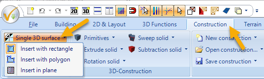
- Select
Construction>Single 3D Surface>Insert in plane.
- Select
-
- Click on the wall in the 3D view.
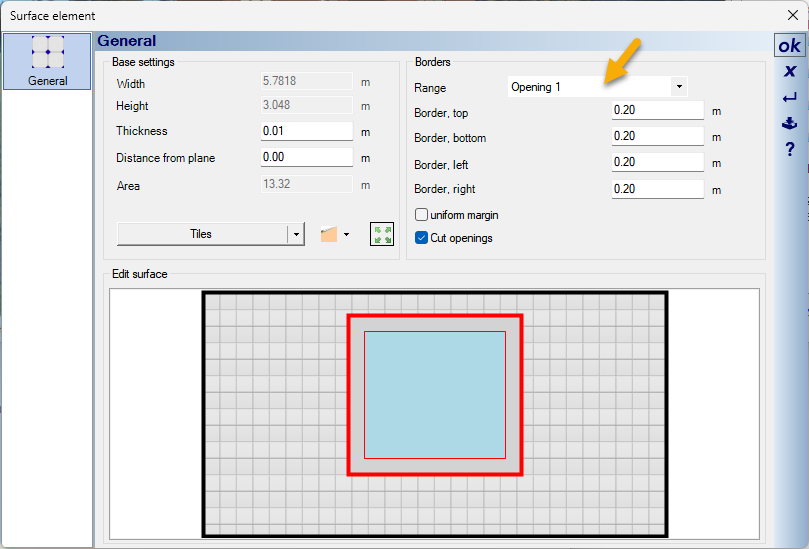
- In the following dialog, set the
Thicknessto a minimal value (e.g.,0.001m) to avoid overlapping. - Define borders and the border around windows/doors in the
Areasection (e.g., usinguniform margin).
- [09:50] Insert with rectangle or polygon:
- Select
Construction>Single 3D Surface>Insert with rectangleto manually position a rectangular surface on a wall. - Select a surface in the 3D view to which you want to form a parallel surface.
- Then draw the rectangle / polygon either in a 3D view, a section, or a 2D top view.
- In the following dialog, define the borders and the border of windows/doors contained in the surface if necessary.
- The newly created surface can be changed most easily in the 3D view by dragging a texture onto the surface.
- Select
3. Area texturing across multiple floors (Section view)
This method is particularly suitable for vertical elements like wood paneling that extend beyond floors:
- [13:20] Create section: Create a section in the 2D view via
View>New Section View. - [14:08] Optimize display: Right-click in the section view >
Properties...> checkHidden line removal. - [15:02] Insert with polygon:
- Select
Construction>Single 3D Surface>Insert with polygon. - Click on an element (e.g., a wall) in 3D to which a new parallel surface should be created, and then draw the exact shape in the 2D section.
- Finish with Right-click >
Complete with Enter.
- Select
- [17:28] Precision through guidelines: If necessary, use guidelines in the section view (under
2D & Layout>2D guidelines>guideline>Numeric parallel guideline) to align the surface exactly.
4. Pro tip: 2D Display in side views
[21:01] Adjust 2D representation: To adjust the appearance of inserted 3D surfaces in 2D plans (e.g., side views), select the created 3D surface with the right mouse button, select Properties... > and then click on the material button (e.g., Tiles). In the following dialog, click on 2D Display. Here you can define the fill styles, colors, and hatchings for the 2D views (e.g., side views).

Further information you find in our video tutorial “Create a side view“.