

Are you looking to design an individual 3D door for your home planning project? In this comprehensive video tutorial, we will show you how to construct your own custom doors using the cadvilla 3D house planner software. First, you will learn step-by-step how to create door leaves from extruded solids, add decorative molding, and precisely position hardware such as handles. Consequently, after saving the finished 3D object, you can easily insert your tailor-made door into any of your future architectural projects.
Note: The functions shown are exclusively included in the cadvilla professional and cadvilla professional plus versions. Furthermore, the zoom functions demonstrated in the video are only valid up to version 5. In newer versions, you can zoom simply by scrolling the mouse wheel. For further details, please refer to our post on zooming in the 2D and 3D view.
Below is a rough overview of the video’s content.
1. Create the base solid of the door
[00:39] Prepare the 2D view
- First, open a new 2D view via
File>New>2D Viewand maximize the window. - Deactivate the
GridandLine widthsettings under2D-Layoutto be able to snap and orientate yourself better.
[01:00] Set guidelines
- Create a grid with guidelines to define the width and depth of the door.
- For this purpose, select
2D-Layout>2D guidelines>Guideline>Vertical guidelineand position a vertical guideline. - Next, draw a
Numeric parallel guidelineexactly to the width of the door (e.g., 1.0 m) away from this guideline. - Then, select
2D-Layout>2D guidelines>Guideline>Horizontal guidelineand position the horizontal guideline. - Finally, draw a
Numeric parallel guidelineparallel to this one with a distance equal to the thickness of the door leaf (e.g., 0.04 m).
[03:36] Create the extrude solid
- Select
Construction>Extrude solid>Insert with Polygon. - Left-click into the 2D view to define the surface. Afterwards, press the right mouse button and select
Properties. - In the properties dialog, ensure
Extrude solidis selected and enter the desired door height (e.g., 2.00 m) underHeight. Confirm withOK. - Draw the polygon exactly along your guideline grid. Next, press the right mouse button and choose
Completeto finish the input.
2. Arrange views and insert a template sketch
[04:53] Create a section view
- Create a section view via
View>New Section View. - Draw the section line spanning across the door. Consequently, the section window will open.
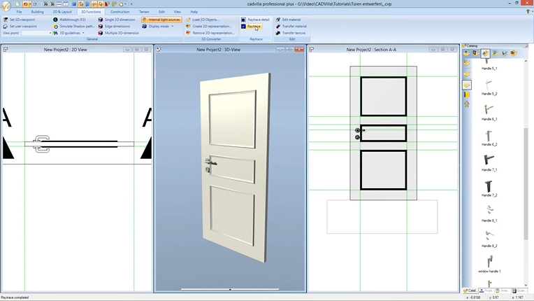
[06:03] Add a 3D view
- Open a new 3D view via
View>New 3D View. Make sure to deselect the ‘Environment’ layer there if needed. - Arrange all three views (2D, Section, 3D) vertically side-by-side on your screen using the
Side-by-sidefunction.
[06:51] Insert an image as a template
- To use an image (e.g., a front view sketch) as a template, select
2D-Layout>Insert bitmap>Rectangle. - Select your image file and draw it as a rectangle natively within the section view.
[07:25] Adjust scaling
- Select the inserted image, press the right mouse button, and select
Adjust scaling. - Click two points whose real-world distance you know (like the door height). Enter the correct target length (e.g., 2 m) and confirm with
OK. - Afterwards, move the image to the background via
Selection>Send to back.
3. Create decorative molding (sweep solids)
[08:19] Set guidelines for the molding (by tracing the template)
- Set further guidelines in the section view natively. In doing so, orient yourself using your image template to properly define the dimensions and spacing of the decorative molding panels using
Numeric parallel guideline.
[11:08] Enter sweep solids for the door panels
- Select
Construction>Sweep solid>Insert with Polygon. - Click on the door surface in the 3D view natively. This specifies the surface to which the sweep solid should run parallel.
- Next, in the section view, press the right mouse button and select
Properties. - In the
Sweep solidproperties underProfile, click onCatalogand choose a suitable profile (e.g., from theDecorationfolder). - Enter the values for
WidthandHeight, choose aReference point, and clickOK. - Draw the sweep solid polygon along the guidelines. Afterwards, press the right mouse button and select
Complete. - Tip: Also note our article for creating your own custom profiles/sweep solids.
[13:29] Copy and rotate decorative moldings
- Activate the 2D view to copy the generated moldings to the back of the door.
- Select the sweep bodies, go to the
Selectionmenu, and selectCopy with reference point. Pressing theCTRLkey allows you to place the copies exactly horizontally or vertically. - To flip the orientation of the copied moldings onto the backside, use the
Selection>Around Z-axisfunction and set the angle to 180 degrees. - In the final step, move the moldings exactly onto the back door surface utilizing the
Move with reference pointfunction again.
4. Add hardware (fittings) and define materials
[15:17] Insert door handles (fittings)
- Define the exact intended position of the handles using guidelines in the section view.
- Open the
Catalogpanel >Component>Windows/Doors>Door & window handles. - Drag a handle holding the left mouse button and drop it into the 2D view.
- Position each individual fitting precisely natively employing the
Selection>Move with reference pointtool. - Tip: Use both the section view and the 2D top view for the exact spatial positioning of the fittings.
[19:24] Edit material and transfer to identical elements
- Select the 3D view and click on
3D-Functions>Edit material. - Click on the desired component (e.g., the door leaf). Now, in the
Default Material Editor, you can adjustColor, texture,Diffuse portion, andHighlight size. Confirm withOK. - Utilize the
Transfer Materialfunction natively under3D-Functionsto apply the exact same settings quickly to other components such as the reglets or panels.
5. Save door as 3D object and edit chunks (important structural step)
[23:23] Export as 3D object file
- Set the 3D view featuring the finished door as the active view (simply click in the view).
- Select
Menuin the top menu >Export>3D Formats>3D Object File.
- Save the door into an appropriate catalog folder via the
Catalogbutton (e.g., typically under AEC\Doors). It is recommended to create a “New folder” for your custom parts. - Caution: Pay close attention to the Windows User Account Control (UAC) warnings. If you save directly in program files with UAC active, the files might be redirected to the VirtualStore pathway (
C:\Users\'User Name'\AppData\Local\VirtualStore\...).
[25:17] Edit Chunks (Crucial for door functionality)
- To ensure the door functions correctly parametrically within walls, you must define the “Chunks”. You need full write access to the file to do this. Therefore, you may need to restart cadvilla as an administrator.
- Select the door within the catalog, right-click it, and choose
Edit Chunks. - Under chunk type, choose
Common Information. Change the operation under ‘this chunk’ toAdd/Replace. Set the Object type toDoor 3D object. - Change the chunk type to
Opening element. Set the operation under ‘this chunk’ toAdd/Replace. - Determine the cut-out natively by clicking on
Find Contour. - Finally, define the
Door hingedetails under object details (e.g.,Single leaf, right-hinged) and set theFrame depth(e.g., 0.04 m) andDepth correction(e.g., 0.0 m) under further parameters. - Confirm everything with
OK. Your door is now fully ready for parametric use!