


 When you look for software to plan and draw floor plans, you will quickly find solutions on the internet. But which software is the right one and what are the characteristics of professional house plan software?
Draw floor plans with floor plan software
We put together a list for you with the most important points for your buying decision.
Floor plan software with extensive basic functions
As a matter of course, floor plan software should naturally master all basic functions that you expect from a decent 3D house planner program. The most important functions are the following:
- Wall input with different wall types and wall thicknesses
- Definition and planning of different wall layer structures
- Input of doors and stairs, binding beams and suspender beams, chimneys
- Input of windows with different dimensions and arrangement of sashes
- Input of ceiling recesses, wall slots and wall recesses
- Support of different roof shapes and dormers
- etc.
Design and draw without any limitations
Nothing is more annoying than finding out all of sudden you cannot keep on designing due to limitations for floors and walls that have to be planned. The right 3D floor plan software has no limitations. With this program you should be able to put in and plan as many floors, walls, doors, windows and objects as you like. Make sure that your hardware is fast enough and has enough hard disk space and RAM because a powerful computer is required for bigger projects.
Parallel display and parallel working in different views
 In order to maintain an overview of a difficult constructural design it is important to be able to display multiple views of one detail simultaneously. The floor plan software should be able to display multiple perspectives on a project next to each other (e.g. a top view, a side view, a sectional view and a 3D view). Any modification and selection in one of the displayed views should be simultaneously displayed in all the other views (in the example on the right the pillars colored red with landings were selected).
For example, you can start a complex wall penetration in the top view and finish it in a sectional view which is adjusted to the penetration. Because this is the only way your work stays efficient and you can maintain a full overview of the project.
Use of modern layer technique using layers

The use of layers (layer technique) has many advantages regarding modern floor plan software. The layer technique allows that different areas are combined with each other and afterwards shown and hidden separately.
The most important advantages of the layer technique using layers are:
- Information can be combined into groups (on owned layers)
- The layers can be shown and hidden, making it possible to create different drawings (for example a design with an existing building and another one with the new building – all in one project).
- Every layer has different heights/levels (for example for galleries on the same floor)
For example, the layer technique is used to display different furnishing proposals. The use of the layer technique also makes sense when you want to structure a project. A layer for the window, a layer for the doors or roofs, a layer for the internal walls etc. and the entire project can be displayed on the printer or screen in different 2D/3D views with differently activated layers.
Modern ribbon surface (quick access tool bar) or tool bars

Decide for yourself!
Modern quick access tool bars (ribbons) have conquered the market after the introduction of Microsoft Office 2010. The ribbon surface facilitates efficient work with focus on the project. The tool bars are combined into groups and always arranged on top.
You will work faster, especially in the beginning using the ribbon surface due to its increased clarity.
The menu navigation via tool bars is also a common form of display in 3D floor plan software programs. Due to the fact that the tool bars are always displayed on the surface you may lose the overview faster, especially in the beginning.
Once you got used to the position of the icons in the tool bars, you can quickly find the functions.
Plan layout with all floors, sectional views and views
 A building application plan usually consists of an overall plan (e.g. DINA1) on which all floors (e.g. ground floor, upper floor, and attic floor), side views (North, East, South, West view) and sectional views (e.g. staircases) are displayed. The 3D floor plan software should include a module for the plan layout with which you can quickly create a plan layout for the building application. Subsequent modifications on the project (e.g. moving a wall or a window) should be taken over in the plan layout automatically.
Creating complex 3D constructural designs and objects on your own
Would you like to display a particular carport, a downpipe, a particular balcony railing or a fitment on your dream house after the completion of the floor planning? This requires a module with which a 3D solid can be designed. 3D solids can consist of solids of rotation or areas that can be cut arbitrarily and be assembled to one object. In most cases it is not sufficient to only create and assemble two-dimensional forms. The floor plan software should include a professional tool in order to create 3D objects and 3D constructural designs.
Light and shadow rendering with ambient occlusion
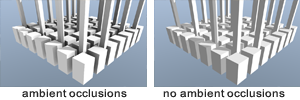 Shadows that become darker as they become deeper are called ambient occlusion. For example, in the image on the right you can see shadows between the cubes. But the deeper you look into the shadow area the darker the shadows become. In the floor plan software an ambient occlusion should be used for image rendering in order to create a realistic 3D display. (For more details click on the image)
Possibilities to export to other CAD programs (optional)
After completion of the floor plan the executing architects, structural engineers and craftsman often would like to take over the floor plan. It saves time and prevents mistakes to take over a floor plan as opposed to putting it in again.
The floor plan software should provide 2D and 3D interfaces for data export. The standard interfaces for a transfer to the 2D area are the 2D-DWG format (AutoCAD) and the 2D-DXF format. The most important transfer interfaces in 3D area are OBJ (Wavefront), 3D-DXF and 3DS format.
Modern development environment Microsoft: NET framework
A floor plan software program should be fully programmed in a modern development environment such as Microsoft.NET framework. The use of Microsoft.NET ensures a trouble-free use of the floor plan software under Windows. CAD programs that include program parts in outdated programming languages such as BASIC or PASCAL can only cope with modern operating systems to some extent because it becomes more and more complex to adjust the programs to the new conditions of the new Windows environments.
cadvilla is a professional software for planning your dream house with an ideal price/performance ratio.


Design your dream house with our professional floor plan software cadvilla professional plus. The CAD software cadvilla professional plus meets all the above mentioned requirements and is the perfect program for planning your house on your own and to quickly gaining a first insight into 3D technology.
Compatible with Windows 10 / 11
Sample pictures
Shown below are a few examples which were created with the cadvilla architecture software.
To enlarge one the following images simply click on it. To close the window which is then opened, simply click on ![]() close window or press the ESC-key.
close window or press the ESC-key.


Customer projects:


