


Basic functions and features
Cadvilla contains many important basic features and general functions that are essential for successful planning. The most important general functions and features of our CAD program can be found in the following overview.
The most important features
(Hint: Click on each feature to learn more.)
Legend for the following table:
![]() ,
,![]() – Feature is included in this version
– Feature is included in this version
![]() ,
,![]() – Feature is not included in this version
– Feature is not included in this version
cadvilla is delivered and installed in 11 different languages (multilingual). Switching the user interface to another available language is always possible.
The cadvilla user interface can be displayed in the following languages:
English, German, French, Spanish, Italian, Dutch, Russian, Polish, Slovakian, Turkish and Hungarian
The software includes manuals in PDF format in English and German.
The cadvilla installation file is running under Windows and contains a 32 BIT and a 64 BIT software package. By default, cadvilla is installed in the 32 BIT version. If you have a Windows operating system with 64 BIT, cadvilla is installed in the 64 BIT version.
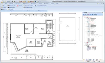 cadvilla uses the same tools to create 2D floor plans in all versions.
In addition to our standard 2D construction elements (walls, ceilings, windows, doors, stairs, …), 2D plans can be finalized and completed with 2D drawing functions (lines, polygons, circles, …), both included in cadvilla.
On top, you can choose 2D symbols from our 2D catalog and easily drag and drop them into your floor plan. More than 1000 2D drawing elements from a wide variety of areas are delivered with cadvilla.
Some examples of the catalog content:
- 2D Symbols for furnishing and exterior design
- 2D electrical symbols for designing electrical installations
- 2D symbols for plumbing plans, create your own heating system, water supply and sanitary system
- 2D Symbols for safety and gas installations
The 2D symbol catalog can be easily extended by using our 2D drawing functions.
Regardless of whether the architectural program is used for floor plans of a new building or a conversion – cadvilla provides the necessary tools.
Building elements of the existing building and conversion part can be displayed in different colours in your 2D floor plan and also highlighted with different fill properties.
The default settings of the architectural software for the design of 2D plans are, by default, adapted to the German industrial DIN and ISO standards. This concerns, for example, the presentation of windows, doors, wall panels and dimension lines.
When entering lengths, these can be entered in different units. You can choose between input in meters, centimeters, millimeters, yards, feet and inches.
For angles, input in degrees or radians is possible.
The output of the lengths (e.g. the dimensioning of the project) can be adjusted according to the input settings. For imperial measurement system, an additional imperial representation and the representation of Feet / Inch can be set for the output. (Example: 7.55 ft or 7 35/64 ft or 7′-6 19/32 “or 7′-6,55”)
You can choose between m², cm², mm², square yard, square feet or square inches for the output of the areas.
For the output of volume you can choose between m³, cm³, mm³, cubic yard, cubic foot or cubic inch.
The desired settings can be saved as default.
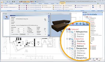
By using cadvillas layer structure capabilities you can combine floors individually in your 2D plans. Elements belonging together can be grouped and inserted on different layers.
Layers can then be faded in or out on each floor plan as you wish with a single mouse click. This allows you to add electrical installation to your floor plan by simply changing the visibility of a self-created “Electrical installation” layer (on which only the components for electrical installation have been inserted).
In all cadvilla versions a project can consist of multiple floors and buildings without any restriction.
cadvilla projects can handle multiple buildings and all of them with an individual level. That allows you to separate your main building and a garage into two buildings, but both still presented on one plan.
In this example, if the main building and the garage have different floor heights and are on different levels, you will need this feature to structure your 3D building model.
By default, cadvilla includes extensive libraries of 2D symbols, 3D models, textures, and materials.
- More than 1000 2D symbols
- more than 2000 high quality 3D objects
All libraries can be easily extended by your individual drawings and constructions or with additional 2D / 3D object collections.
- More than 5500 high quality textures
- more than 1000 high quality materials
Each material can contain different textures and be mixed with any color in adjustable intensities.
There are almost countless possibilities for the design of surfaces. Custom textures or scans can be added to the texture catalog with just a few clicks.
Our 3D visualization can be refined by using additional functions like ambient occlusion and smooth shadows for light sources so that the 3D building becomes more and more photo-realistic.
By adding a background image of the real plot, this effect can be enhanced.
In addition to the normal light / shadow calculation, ambient shadows can be calculated in all versions. This process makes the calculated images even more photo realistic.
Ambient shadows are shadows that appear darker in depth. The further a shadow is away from the sunlight, the darker it appears.
A classic example of this is a cave that lies in the shadow. The further you go into the cave, the darker it gets inside.
In the ambient occlusion calculation, all 3D elements contained in your 3D scene (walls, windows, doors, roofs, balconies, 3D furniture, 3D exterior objects, etc.) are taken into account.
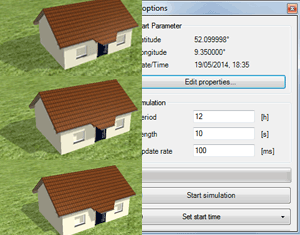 In case of a shade simulation the start and end time of the simulation is defined in a dialog as well as the geographical location of the building project.
Afterwards you can follow the course of the shadow casting in 3D view via the defined period of time like in a video.
In the adjacent image you can see the dialog window and 3 screen shots of a simulation during 9:00 and 11:30 a.m.
Using this function you can for example check the planning of photovoltaic systems. The simulation helps you to place the photovoltaic elements the right way and to generate the maximum energy from them.
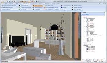
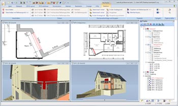 In principal, the software operates based on a 3D model for which various views can be defined.
The following illustration shows a 3D perspective view and a 2D plan view. Several windows with different content can be displayed at the same time.
Since internally all views are equal, all user actions, e.g. selecting,, positioning, moving etc. are, if applicable, carried out the same way in all views. All views are updated simultaneously so that the user can follow the effects of changes in 3D as well as in 2D.
The individual windows can be presented vertically or horizontally tiled, cascaded or in tabbed form.
 ‘Walkthrough’ mode can be activated in an active 3D view.
In this mode, direction and inclination are controlled by movements of the mouse. The mouse wheel can be used to change the height of the viewing position.
You can control forward and sideways movements by default with the arrow keys. Other key combinations and further options can be specified in the ‘walkthrough’ dialog.
If you press the SHIFT key during a movement, movement of the adjustable factors are accelerated.
 With our architectural software, you can not only draw 2D floor plans and visualize them in 3D, but also add 3D objects for interior design and exterior areas.
The 3D models for interior or garden design can be freely scaled, distorted and coloured. The accurate positioning can be done either in 2D or 3D views.
With cadvilla professional or higher it is also possible to import 3D models from external formats such as 3DS, Collada or SketchUp.
This gives you access to millions of 3D objects from various manufacturers and allows you to quickly build your own 3D objects collection according to your wishes.
The architectural program Cadvilla not only becomes your floor plan tool, but also your interior designer and garden planner.
Our project wizard allows you to quickly create a single room or building shape in a few steps by just editing some parameters.
General basic functions – available in all versions
Constructive basic functions are used to draw, construct and create homes, apartments and other buildings and are included in all cadvilla versions. The following compilation shows an overview of the most important functional details.
The most important basic constructive functions
(Hint: Click on each function to learn more)
Legend for the following table:
![]() ,
,![]() – Feature is included in this version
– Feature is included in this version
![]() ,
,![]() – Feature is not included in this version
– Feature is not included in this version
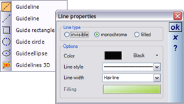 Different types of auxiliary lines and input options are provided for 2D plan views and 2D views/sectional views.
There is a difference between a straight line and a straight length. Straight lines are ‘infinite’, while a straight length has a start and an end point. You will notice this immediately due to the different input options.
All types of auxiliary lines can be turned off in any view using the visibility option for construction aids.
The color properties and style properties can be set for all types of auxiliary lines. These properties can be modified later, and can also be specified when the auxiliary lines are created in the property dialog which is activated via the context menu opened with a right mouse click. The advantage of doing so, while the auxiliary lines are created, is that they have the right properties automatically, and do not have to be modified later.
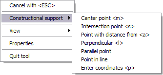 The program allows you to create any complex scaled floor plans. Grids, auxiliary lines, and options for numerical input are provided for input purposes.
Additionally, there is a context menu providing construction aids in order to capture data. They are particularly helpful for constructing with the help of a midpoint, an intersection point, a point at a distance of, a perpendicular, a parallel point, and a point in line or coordinates.
The construction aids are available for all inputs, for example for inserting walls, windows and doors, and they allow you to quickly create a floor plan.
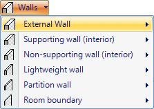 When entering walls, you can choose between the following wall types.
- External wall
- Supporting wall (interior)
- Non-supporting wall (interior)
- Lightweight wall
- Partition wall
- Room boundary
For each wall type, a standard is defined, which contains the wall thickness, the material, the line type, the filling pattern and the layer structure. These parameters can be changed at any time individually by changing the ‘Walls’ properties for individual walls.
For each floor of the building the software automatically creates a ceiling over the first exterior contour of connected rooms.
In some cases automatic ceilings are not necessary or desirable. Therefore, they can be deactivated for one floor in the properties dialog of the particular floor. Additionally, the creation of an automatic ceiling can be turned off when a floor is copied.
In addition to automatic ceilings, ceiling slabs can also be inserted using a rectangle or polygon.
As with all construction elements, structural layers can also be defined for ceilings.
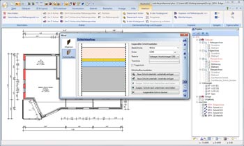
Construction components such as walls, roofs and floors, contain structural layers with their own properties. By default, for each of the components mentioned above, at least one layer is always defined.
You can create other layers created and modify their properties. You can specify a name for each layer, the thickness, the building material, a layer separator and the location of the layer within the structure. Multi-layered structures which are frequently used can be saved in the provided folder for future use in other projects.
Once you have defined a wall, it is shown in the 2D view with the appropriate fill patterns, layer thicknesses, hatchings, colors, font sizes and line types.
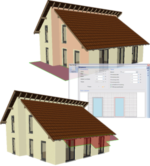
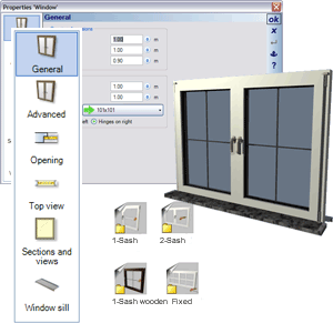 The software offers a selection of various window types. They range from windows with one or two casements, with or without bars to windows with predefined materials and standard windows.
If you move the cursor over the plan in the vicinity of walls you can see a preview of the window you put in including the direction of opening.
You can position the window by using auxiliary lines or construction aids.
Construction aids are particularly useful for constructing via a midpoint, an intersection point, a point at a distance of, a plumb bob, a point with parallel extension, and a point in extension and the input of coordinates.
You can specify the width, height, direction of opening, and sill height of the selected window in the properties dialog along with the display of the top view, the opening, the sectional views and the other views.
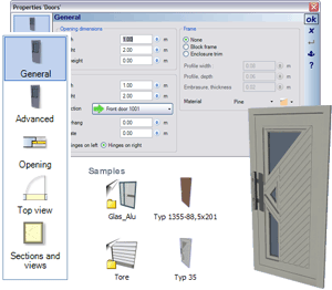 The software offers a large selection of different door types. They range from standard doors to glass doors and gates.
If you move the cursor over the floor plan, in the vicinity of walls, you can see a preview of the door you have selected to put it in.
You can then position the door with the help of auxiliary lines or construction aids.
Construction aids are particularly useful for constructing via a midpoint, an intersection point, a point at a distance of, a plumb bob, a point with parallel extension, and a point in extension and the input of coordinates.
You can specify the width, height, direction of opening, and sill height of the selected door/gate in the properties dialog along with the display of the top view, the opening, the sectional views and the other views.
You can also specify these properties as a default for other projects.
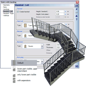 Once you have put in stairs, the program automatically calculates the width and height of the staircase, and based on the step dimensions, a reasonable ratio between rise and tread depth. These values can then be modified in the subsequent input dialog.
All stairs can be constructed with a solid or a wooden staircase. Different input fields are provided depending on the construction type. In all staircases handrails can be modified on the right and left. The changes do not only apply to the dimensions of the handrail components, such as ‘handrail’, posts, steps and base rails,, but also the shape of a component can be selected from a number of predefined shapes.
When putting in stairs with landing individual landings are created automatically at each corner of the polygon. A defined minimum distance between landings, defines at which point the software creates stairs between two landings.
For the individual display of stairs in the 2D top view you can choose between standard, lower part visible, upper part optionally visible, and display of stairs with separation lines.
Chimneys start on the floor in which they are put in and extend upwards through all upper floors and the roof.
The option to change the height later either define an absolute height in relation to the floor where the chimney is located, or a relative height above the highest ridge of the roof defined for the current building. You can also define the absolute height for a chimney.
Under structure you can specify the number and the dimensions of vents, as well as an option for ventilation.
By default, the 2D display of the chimney in 2D top views depends on the shape of its 3D model. Other displays can be allocated using 2D symbols from the catalog. A display using a symbol is automatically scaled to match the absolute dimensions of the chimney.
Putting in beams above or below a ceiling is like putting in walls, i.e. they join up and can be put in as a polygon or individually between two points.
Beams below a ceiling are automatically placed underneath the ceiling; beams are placed on the ceiling structure and thus also modify the floor of the room.
Apart from the width and height of the beams you can specify the line type for display, the material for the upper, lower and exterior surfaces, and structural layers.
Supports can have a round or rectangular profile. Both forms can be positioned freely with a single mouse click. The dimensions of the support, the representation of its outline and the building material and its characteristics can be specified in the ‘Properties’ dialog. By default, supports automatically assume the height of the floor of the building and the level of the layer in which they are put in.
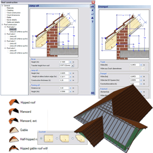 The program allows for the automatic or manual construction of hipped end roofs, gabled mansard roofs, extended gabled mansard roofs, gable end roof, clipped gable roof, and clipped gable roof with a whole, ridged roof, monopitch roof as well as a combination of these roof shapes.
Furthermore, the roofing, timber construction, rafters and details of the gable ends and eaves are automatically constructed once the roof has been defined.
The program automatically makes recommendations for the roof structure, including roofing, timber construction, rafters and details of the gable ends and eaves.
The associated roof editor simplifies the definition of new, complex roof shapes.
You can define a profile type, e.g. a gable end roof, a monopitch roof, a hipped end roof, a clipped-gable roof, for each roof area. Depending on the selection, the required parameters are retrieved and explained immediately by a 3D display.
The ability to define the attic wall sill and inferior purlins for each roof area is another feature of the roof construction.
You can define a particular shape for visible purlin heads from those defined under gable end details.
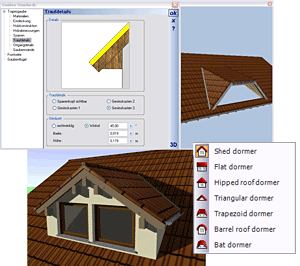 The dormer function allows you to put in various dormer types in existing roofs.
Possible dormer types are gable dormers, swept dormers, hipped dormers, triangular dormers, trapezoidal dormers, arched dormers, and eyebrow dormers.
Dormers and their walls and framing are fully integrated into the roof.
The dormer walls and roof are automatically created when the dormer is defined. Modifications to the timber construction of the roof are subsequently taken into consideration. The rafters are removed in the area of the roof where the dormer is inserted, and the rafters for the dormer roof are also constructed.
If necessary, you can of course modify and amend the dormer via various settings parameters later.
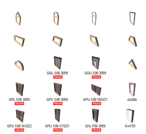 The software provides an extensive selection of roof windows of different types and styles (an extract is shown in the illustration on the right). Of course, roof windows from the manufacturer velux ® are represented as well.
You can add in roof windows in 2D and in 3D views. In the process the roof window turns automatically in the direction of the roof side where the window is located, displayed transparently and thus allowing the view to the underlying rooms and timber constructions.
When roof windows are inserted, matching openings in the timber construction are created automatically. The dimensions of the timber for the openings are identical to the dimensions of the rafters specified in the ‘Roof’ dialog.
Roof windows can be positioned freely within a roof area using the mouse. The calculated position of the roof window can be numerically adjusted with regard to the sill height and the opening height, in the properties dialog for the roof window.
The labeling of the created rooms may contain the following automatically determined values in addition to the room name:
- Net floor area according to DIN277
- Living space according to WoFlV
- Floor area
- Volume
- Floor outline
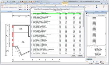 In the case of the area and mass determination all elements included in the planning (rooms, walls, windows, doors, pillars, ceilings, chimneys, roofs) are listed in a clear tree structure. When choosing individual elements from the tree structure the properties such as dimensions, areas, volumes, formulas etc. are displayed in the detail window, and in the floor plan the element is marked red accordingly.
This way you have – in addition to the detailed display of masses – also visual control in the 3D view.
An entire presentation of masses as part of the project can be created in form of a table/list in different formats (Excel, PDF, RTF). This way you can create for example a list of all walls including all masses and areas for further calculation and proposal preparation by generating an EXCEL file.
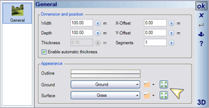
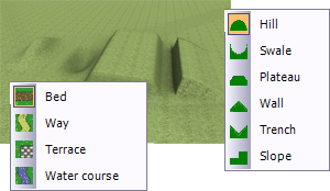 The software provides a range of predefined landscape forms such as hills, declines, plateaus, ridges, gutters and slopes to allow you to shape the terrain. Suitable dialogs are provided for putting in the various terrains.
Other landscape features can be incorporated as well. The available features here are flower beds, paths, terraces and waters. Here you are supported by adjusted input dialogs – thus, paths can be put in polygonally or in the shape of splines. Landscape features automatically adjust to the contour of the terrain and the terrains defined.
 Using this function, satellite images, aerial photographs and in fact any image can be customized to match the terrain with just a single mouse-click.
For instance, you can save detailed satellite views of your property from the internet and then simply drag them onto the terrain. The image can then be tailored to match the property using the properties dialog for the environment.
Tip: Particularly suitable as background images are, for example, a street view or a 3D view (Earth view) of the area.
 The surface editor can be used to create 3D surfaces on various planes.
Once a plane or surface area (e.g. wall, roof, surface area of an item of furniture) has been selected, a parallel surface area can be created in the shape of a polygon, a rectangle or a parallel plane.
In the subsequent dialog for the surface created you can specify the thickness of the surface and the distance from the selected plane.
Whenever a surface area is defined, first of all openings such as windows, doors or wall recesses included in or under the surface are detected and shown in the dialog.
Examples for the use of the surface editor are
- Façade cladding
- Wall tiles for kitchens and bathrooms
- Window surrounds
- Terraces and other features for exterior design
- Work tops
- Additional roof elements
- And many more
There are four ways of measuring:
– Measurement between 2 points (distance)
– Perpendicular measurement according to the selection of the reference component e.g. the wall side
– Measurement of a polygon
– Measurement of angles
During input, the current values such as angle and distance are continuously updated at the measurement line. A left mouse click terminates the measurement process and the result is shown in the plan, until another measurement is performed, or the measurement function is terminated with ESC or via the context menu.
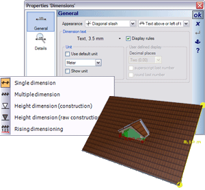 The software differentiates between single, multiple and height dimensions (for sectional views and other views).
The settings for a dimension, regarding type, style and text can be modified for an existing dimension, or during input for all following in the properties dialog for ‘Dimensions’.
As a default, the display of dimensions according to DIN 1356 is active. In a rather simplified way, the dimensions are then created as follows:
– Measurements greater than 1 meter are shown in meters with 2 factional digits. Values that follow in cm which must be rounded to 5 are denoted by a 5 in superscript.
– Measurements less than 1 meter are shown in cm. Values that follow in mm which must be rounded to 5 are denoted by a 5 in superscript.
The function ‘Copy Properties’ is provided to change the settings for several or all dimensions later.
The 3D dimension types are available in all 3D previews shown in dialogs. However, here they serve more than a measuring device, since the dimensions are lost when the preview or the dialog is closed.
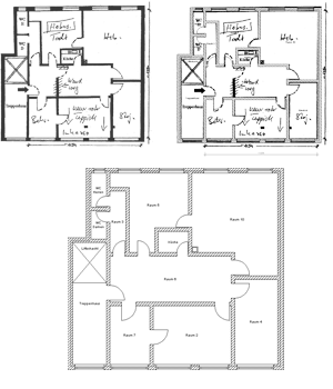 Images and 2D Elements can be scaled very accurately. This allows images of floor plans to be added in and used as a ‘blueprint’ on which the 3D model of the building can be constructed.
The procedure for creating a 3D model is quick and easy.
- Load the image of the 2D floor plan:
Load the image from a JPG, BMP, PNG or GIF file. - Scale the image:
The image must be scaled to the correct dimensions, as undefined dimensions and incorrect proportions can often result during input.
You can achieve this by putting in a reference dimension which is defined by specifying two endpoints in the image. Then a dialog box will appear that shows the current measurement while allowing for a numerical input of the actual value. After exiting the dialog the image is scaled to the new dimensions. - Input of the 3D model of the floor plan:
You can now start with the input/blueprint of the floor plan. Measurements for wall thicknesses, windows and doors can be taken directly from the inserted image using the measuring and dimensioning functions provided.
In order to make the 3D visualization as realistically as possible, you can set a photo of the real estate environment as a background in the project.
In the 3D view, you can then “turn the 3D model into the image” and so you have a first virtual view of your new home in the real world.
Ray tracing (light and shadow rendering) in 3D views is an important feature of cadvilla. Ray tracing takes into account all visible elements and objects in the scene and their current settings.
The available settings for ray tracing have a considerable effect on the quality of the representation. These settings include anti-aliasing, smooth shadows and ambient shadows, the intensity which you can specify before ray tracing is activated.
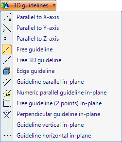 The software provides various types of 3D auxiliary lines to support the input in 3D views:
- Guidelines parallel to x-, y- and z-axis
- Free guideline and edge guidelines
- Guideline parallel in-plane
- Numeric parallel guideline in-plane
- Free guideline (2 points) in-plane
- Perpendicular guideline in-plane
- Guideline horizontal and vertical in-plane
When creating 3D auxiliary lines, the current position is shown by a 3D cursor, which snaps to surfaces, edges and corners. In order to help create auxiliary lines relative to axes, and for all straight auxiliary lines, the line itself is displayed directly.
This feature allows you to enter your own text in views, or to load and format text files. Furthermore, you can specify an angle for the complete text block.
The autotext feature provides placeholders for values which change from one project to another such as project name, name of planner, etc. The autotext placeholders provided consist of the properties of the views such as name and scale and the project properties, for instance names, addresses and remarks for the planned building, the planner and the client.
Using the autotext feature and the save text function, you can create text blocks for the use in future projects without having to change project related values manually. Using 2D symbols and the standard graphic functions, other applications, such as titles and legends are also possible.
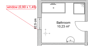 Item text can be used to label elements (for example, windows, 3D objects and walls) by positioning a text with a line connecting it to the selected element. If several elements overlap, a particular element can be selected over the context menu.
All properties of an item text such as the content and style of the text can be changed, if necessary, in the dialog which is activated by double-clicking on the item text or via the context menu available for a selected item text.
With the help of these functions you can add additional details such as lines, polygons, rectangles, circles and ellipses to 2D views, i.e. top views, sectional views, views and parallel perspectives.
This enables you to add planning details to your drawings for the specification of for example sanitation and electrical installation.
The elements used in the 2D graphic editor, i.e. lines, polygons, rectangles, circles and ellipses, have various properties for display which can be defined in the corresponding dialogs and which include the thickness of lines and borders as well as properties for edges and fill patterns.
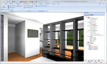
 The new function “3D raster elements” in the section “Surface planner” serves the purpose of covering surfaces (e.g. walls, floors) that should be covered with 3D elements in an evenly distributed manner as rows and columns.
Typical application areas for the function “3D raster elements” are for example facade claddings, mirror tiles, representation of floor plates in the outdoor area, wood panels, thermal insulation and many more. With just a few mouse-clicks individual walls up to entire building facades are veneered with 3D surfaces, or its terrace surface are covered with timber floor boards.
Openings in walls (e.g. window and door openings) are considered and can automatically be left out. The remaining surfaces arising from this are automatically added by partial surfaces from the 3D elements.
Profiles for the installation of the 3D elements can be created additionally and can automatically be inserted between the rows and columns. The cross-section of the profiles is selected from a pre-defined catalog or can be created on your own as well.
The created 3D surfaces can be provided individually with different textures and materials, but also in separate columns or rows.
Each included 3D element can be further divided into sub-surfaces with different dimensions and can manage its own materials.
After selecting a placing area in the 3D area of the 3D raster elements, you will receive a parts list of the placed 3D elements with the respective measurements. Identical 3D elements are added up in terms of their number and are summarized.
This function is particularly useful for adding light sources to existing and new objects.
The software differentiates between the following:
- Ambient light sources
- Directional light sources
- Spot lighting
- Punctual lighting.
Ambient light sources illuminate all areas of a scene equally and therefore increase the overall brightness. However, they do not create shadows.
Directional light sources illuminate a scene from only one direction and are ‘internally’ infinitely distant from the location of the observer/building. The sun is an example of a directional light source.
Punctual light sources have a defined position within a given object and are therefore the closest display of real lamps for interior decoration. The scene is illuminated in all directions around the light source.
As with punctual light sources, spots have a specific position within the given object and therefore also represent real lamps. However, in this case the light does not emanate in all directions as it is the case with a punctual light source, but instead in a light cone with a beam angle and aperture angle.