Easily create an escape plan and draw emergency evacuation plans
 Marking the escape and rescue routes is an important part of a building’s safety features and must be included in every fire prevention documentation (see also ISO 16069). In case of fire or an emergency; the escape plan should graphically display the fastest way to the next possible exit, and should, at the same time, include important information about how to behave in case of fire. Furthermore, it should be installed in easily visible places.
Emergency evacuation plans, emergency and fire exit location plans, and fire escape plans in workplaces and in public institutions must be installed where required by the extent, the location and the type of use. The contents and execution of the plans are described in the workplace regulations ASR A1.3 and ASR 2.3
The extensive module escape and rescue routes planner is a Windows program for the CAD software cadvilla and allows you to draw fire escape plans, emergency and fire exit location maps, and emergency evacuation maps according to DIN ISO 23601 (standard for safety marking for escape and rescue plans), DIN EN ISO 7010 (European standard for safety signs) and DIN 4844-2 as well as the creation of planning documents for firefighters according to DIN 14034-6 (graphic symbols for fire brigade response plans and fire brigades) and DIN 14095 (requirements for fire brigade response plans for structural works)
The module is intended as an extension to our CAD software cadvilla. The drawing program cadvilla is a high-quality house plan software that you cannot only use to create 2D plans, you can also visualize and walk through entire building complexes in 3D.
The software extension for creating escape and emergency evacuation routes includes a comprehensive and expandable catalog with required 2D symbols such as fire prevention sign, rescue signs, mandatory and prohibition signs, warning signs and fire protection signs as well as diverse tools that especially help you designing an escape plan.
The following description demonstrates how to handle each tool, however, does not include any instructions for executing escape and rescue plans according to DIN ISO 23601 or other standards and provisions.
The functions of the extension module at a glance
The additional Windows module is primarily based on the assumption that a floor plan of the building will be generated or has already been generated with the regular functions of the CAD software cadvilla.
For the emergency evacuation plan, emergency and fire exit location plan, and fire escape plan, the final floor plan should be reduced to the basics. However, all constructive elements such as walls, stairs, windows and door should be included.
Our tip: in case the floor plan must be entered beforehand: For a quick capturing of a floor plan, utilize a deposited image of the floor plan (tracing of a scanned plan), or the DXF import included in larger cadvilla versions (trace plan in DXF/DWG format).
The extension module for a color design includes the following performance features:
- Wizard to generate an escape and emergency evacuation plan, emergency and fire exit location plan, and fire escape plan view
- Draw functions for arrows
- Function to mark the location
- Generating legends by means of signs used in the emergency plan such as e.g. mandatory signs, prohibition signs, fire prevention signs, rescue signs, warning signs or fire protection signs
- Simple color marking of walls and rooms
- Comprehensive catalog with all required signs to create an escape and emergency evacuation plan, fire escape plan, and emergency and fire exit location plan

Your own Emergency evacuation plan / emergency and fire exit location plan / fire escape plan
Below, we will show you how to create plans for the escape and rescue routes step by step using our Windows software. When drawing your plan, always make sure to observe the regulations of the relevant valid standards such as e.g. DIN ISO 23601 or DIN 4844-2.
Preparing the project – deciding for horizontal or vertical format
 By default, escape and rescue plans are in horizontal format. In case your property has rather been planned for a vertical format, it should be rotated beforehand. For rotating a building, cadvilla offers the respective functions in the sections Edit -> Edit building
Note: As various structural elements and dimensionings are not considered when rotating a building, your project could thus be negatively affected. Therefore, create a copy of your project prior to rotating the building and create escape and rescue plans only based on this copy.
Wizard for creating the escape and rescue plans
If the overall floor plan, an extract of the floor plan or also the individual floor is rotated matching the horizontal format of an escape and rescue plan, start with the wizard included in the additional module of the software.
The wizard contains the following functions:
- Language selection: The language of the headline in the escape plan is set using the selection. You can choose between German and English. In English, the headline would be “Fire Escape Plan” instead of “Escape and Rescue Plan”. If you would like to use an own frame, you can always do that later in the finished 2D view.
- View: In this section, you can define which areas and floors of the entire building should be displayed in the escape and rescue plan. The options make use of the visibilities of the project viewer in the right-hand side of the basic software and can be modified later and anytime.
 Scale: With our CAD software cadvilla, all elements can be marked to scale. However, this is not strictly necessary in case of plans for escape and rescue routes. The scale should rather be aligned to the selected paper format.The wizard automatically calculates the scale of the selected paper format for a maximum representation of the floor plan. Then, the scale can manually be modified. In the preview, the floor plan will be automatically adjusted to the selected scale within the drawing frame.Additionally, you can move the drawing frame in the wizard in adjustable steps with the arrow buttons by the floor plan and position it this way.Of course, you can change the scale and position the drawing frame also later in the generated 2D view.
- Wall representation: In construction plans, walls are mostly represented with a complete layer composition. However, this makes escape and rescue quickly look overloaded and thus less attractive.By selecting a corresponding wall color, you can display the walls filled with one color. The project itself will not be affected by this, only the walls will be “painted over” in the resulting view.
Placing 2D symbols from the catalog
The special symbols for the escape and rescue routes are located in the area of the 2D graphics where they are sorted into a folder and in different sub-areas. The sub-areas are divided into:

- General symbol signs
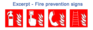
- Fire prevention signs, general symbols for fire prevention
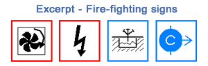
- Fire-fighting signs, general symbols for fire-fighting plans
- Mandatory signs and tags (blue)
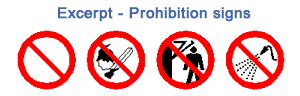
- Prohibition signs and tags (red)
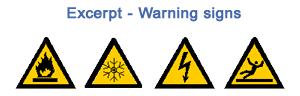
- Warning signs and tags
- Rescue signs and tags (green)
- Legends and drawing frames

The catalog includes a total of 250 symbols. The signs are located and accurately placed in the escape plan, rescue plan and also in the fire-fighting plan simply by means of the mouse via drag and drop (select signs, then click and drag the mouse in the 2D view).
Tip: According to ISO and DIN standard, the signs entered in the escape or rescue plan should in any case contain the exact
- location of the emergency and rescue equipment,
- location of the fire-fighting resources for fire prevention and
- position of the meeting point for the escaping persons in case of emergency.
Insert and place legends
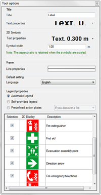 In case of legends, we distinguish in our additional program between three different types of legends that can be selected via the legends dialog and can then be inserted in the 2D view via drag and drop.
- Legends from planning: This option examines the 2D view and lists all symbols used in the plan in an overview such as rescue signs, fire prevention signs, safety signs or mandatory signs. Via checkboxes, you can select which signs should be included in the escape plan, rescue plan or fire-fighting plan.
- Individually created legends: This option lists all escape and rescue signs available in the software. You can determine yourself which symbols should be displayed in the legend.
- Pre-defined legends: There are two pre-defined legends
- Behavior in case of fire: Notification of the fire, get to safety, attempt to extinguish the fire using fire-fighting resources
- Behavior in case of emergency: Issue alarm, take immediate measures, get to safety
The pre-defined legends can, of course, also be extended and supplemented by your own legends as required and will later be available universally.
Representing escape and rescue routes by arrows – setting the location
In addition to cadvilla’s draw functions, the program module for the escape route planner also contains a special function for drawing straight and angled arrows. The pre-set color green for the arrow as well as the width are defined prior to inserting the arrow via the settings dialog in the context menu. When drawing a straight arrow, the start and end point is requested – in case of an angled arrow, the start point, the corner point of the kink and then the end point.
A special location symbol enables you to draw your current location in the escape plan. Also here, you can call up the properties dialog via the context menu before the point is set, and there you can modify the pre-set color blue and the diameter of the symbol according to ISO standard.
Wall representation – painting over walls in the escape and rescue plan
Similar to the wizard, the texturing of the wall can be changed or painted over again later.
Color representation of rooms
According to ISO and DIN standard, it is required to highlight the rooms along the escape and rescue route in the plan. This can already be realized by the standard functions in our CAD software cadvilla. But our software component Escape and rescue routes plan provides another, very convenient option. You can define the target color via the item “Color Selection”, by means of the item Coloring Rooms, the r ooms are filled with color with just one mouse click on the cursor position.
This function maintains active until it will be terminated by ECS button or via the context menu of the right mouse button. This way, you can quickly and easily mark multiple rooms in a passageway in color.
If you only want to mark parts of rooms in color, utilize the 2D draw functions included in the standard program such as rectangle or polygon and set your desired target color in the filling properties.
Switching visibilities of escape and rescue elements on and off
When using the software module “Escape and Rescue Routes Planner”, all used symbols, signs, texts, legends, frames and markings will be allocated to an individual visibility category and can therefore be switched to visible or invisible separately.
For a regular floor plan, you should leave the category Escape and Rescue Route Plan switched off.
Creating your own escape and emergency plan – This software makes it work
 This easy and intuitive way of creating rescue plans for workplaces or other buildings will fascinate you. Draw your plans for rescue and escape routes or fire-fighting plans now on your own Windows PC!
The additional software Escape and Rescue Routes Planner requires an existing installation of the CAD software cadvilla under the operating system Windows.
3D CAD software for the professional planning of buildings
Now plan office buildings or other real estates on your PC with the professional 3D CAD planning software from cadvilla and at the same time save money by the current offer!
We have the right software solution for you! The prices range between € 39,95 – € 219,00 incl. VAT * *
![]()


*