


(Note: The upgrades listed below require an existing cadvilla version 6 or higher.
For possible upgrades of older versions (V1 / V2 / V3 / V4 / V5) including pricing, please contact our sales team)
cadvilla
basic
Upgrade
Existing
cadvilla basic
➔
cadvilla basic
13.0.7.0
(Regular € 45,95)€ 39,95 *
cadvilla
basic plus
Upgrade
Existing
cadvilla basic plus
➔
cadvilla basic plus
13.0.7.0
(€ 59,95 *Regular € 69,95)
cadvilla
professional
Upgrade
Existing
cadvilla professional
➔
cadvilla professional
13.0.7.0
(€ 67,95 *Regular € 124,50)
cadvilla
prof. plus
Upgrade
Existing
cadvilla professional plus
➔
cadvilla professional plus
13.0.7.0
(€ 78,95 *Regular € 149,50)
![]()
*
Upgrade and switch to a larger version of cadvilla at the same time
You want to extend the scope of your version and upgrade to a larger version? Here you will find all possibilities.
Additional features of cadvilla version 13
The additional features of cadvilla V13 listed in the following table only represent the most important changes compared to cadvilla V12. Of course, many other smaller modifications and enhancements, as well as the elimination of certain weak points, have also been implemented.
Legend for the following table:
![]() ,
,![]() – Feature is included in this version
– Feature is included in this version
![]() ,
,![]() – Feature is not included in this version
– Feature is not included in this version
With the electrical planning assistant, planning the electrical systems for your construction project is easier and more efficient than ever before. This powerful tool offers you a variety of advantages that not only simplify your work but also speed it up.
The electrical planner is specifically designed to optimize your workflow. It reduces effort by saving you hundreds of clicks through catalogs, while also giving you the ability to refine your planning down to the smallest detail.
Why is electrical planning easier with the new assistant?
- Time savings: Fast and easy planning without unnecessary clicks through extensive catalogs.
- Flexibility: Individual adjustments and custom variants.
- Efficiency: Floor-by-floor planning for maximum clarity.
- User-friendliness: Intuitive operation and clear previews.
Highlights of the electrical planning assistant in detail:
1. Fast and easy electrical planning
The new electrical planning assistant enables you to insert and place 2D symbols such as sockets, switches, and lights into your project in no time. Once your building and floor plan design is complete, you can equip the entire building with electrical components in just a few steps. This saves time and significantly reduces effort.
Thanks to intelligent room assignment, you can equip rooms with predefined equipment variants. Simply select the room type and the desired variant—the assistant takes care of the rest. This way, you avoid tedious manual placement and can focus on fine-tuning.
2. Custom equipment variants
Adapt the electrical equipment of the rooms individually to your needs. With the ability to create and save custom variants, you can easily cover recurring requirements and standardize your planning.
3. Efficient workflow – floor-by-floor planning
The electrical planner is perfect for large projects. The best way to work is floor by floor, by making only the current floor visible. This way, you maintain an overview and can implement the electrical planning step by step efficiently.
4. Intuitive operation and preview
The preview in the assistant provides you with a clear representation of the rooms, including walls, windows, and doors. Place symbols freely or use installation suggestions to position sockets and switches precisely. The intuitive operation ensures that you keep an overview, even in complex projects.
Take advantage not only of the extensive electrical symbol catalogs provided by cadvilla, but also enhance your planning by adding your own electrical symbols. Furthermore, you have the option to create catalogs with your own electrical symbols. This keeps you flexible and allows you to easily meet individual requirements. Custom electrical symbols offer you maximum flexibility and open up new possibilities for planning and implementing your projects.
The advantages at a glance:
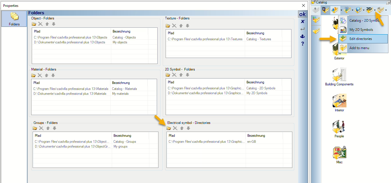 Individual customization: Use your own 2D symbols and define them as electrical symbols. This allows you to design your projects exactly according to your ideas.
- Easy integration: With just a few clicks, you can add your own directories and integrate your symbols directly into the electrical catalog.
- Clarity: Assign individual names to your catalogs so you can quickly and easily find your symbols.
- Maximum flexibility: You can add as many directories as you like, expanding your personal symbol library.
- Efficient workflow: The clear structure and easy operation save you valuable time during planning.
How it works:
- Create your own directories with 2D symbols.
- Add these directories to the “Electrical Symbol Directories” category using the intuitive directory settings dialog.
- Assign individual names to your catalogs to optimally organize your symbols.
- Use your own electrical symbols directly in your projects—simply via drag-and-drop.
With this feature, cadvilla gives you the opportunity to take your projects to a new level. Whether you are a professional or an ambitious planner, the ability to use your own electrical symbols not only makes your work easier but also significantly more professional.
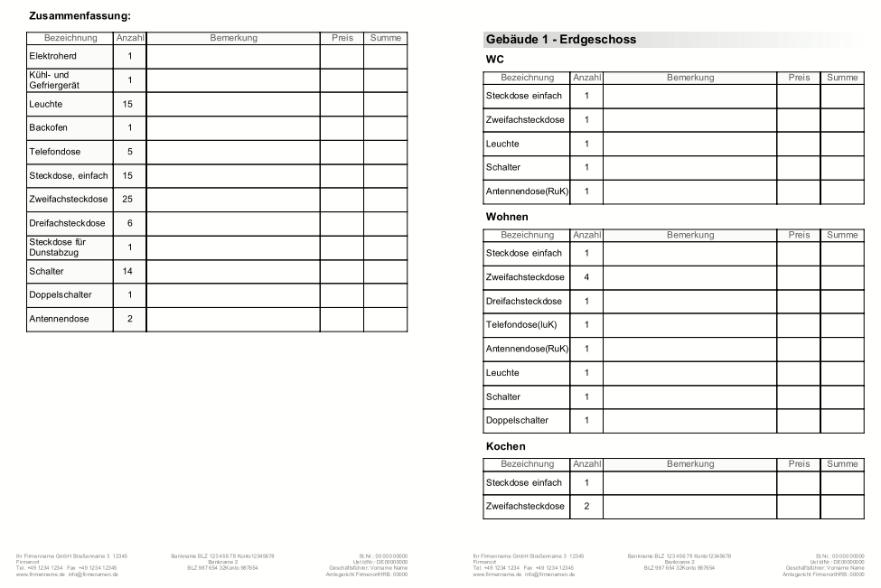
With the new electrical planning feature in cadvilla, you not only receive precise plans and drawings, but also a clear bill of materials listing all used elements. This feature provides you with a concise and well-structured summary of your electrical planning—perfect for professional and efficient project execution.
Your benefits in detail:
- Automated bill of materials creation: The bill of materials provides a complete overview of all electrical symbols used in the project. Additionally, it offers a practical breakdown by rooms, which greatly simplifies planning and organization.
- Flexibility for further processing: The fields for description, price, and total can be customized individually. This allows you to adapt the bill of materials to your needs—ideal if you want to export the data as an RTF file or Excel spreadsheet.
- Easy operation: The bill of materials can be generated intuitively via the menu Output ⇾ Reports ⇾ Lists. This makes the feature quick and easy to access.
Use these bills of materials for electrical planning to implement your projects even more efficiently and professionally!
With the advanced door functions, we are setting new standards in the design and planning of doors. Whether sliding doors, folding doors, or doors with asymmetrical wall openings – our software now offers you even more flexibility and precision.
Thanks to the new option to assign a custom subtraction body to door objects, you are no longer bound to the size of the 3D object. This means:
- Sliding doors with rail systems can now be represented realistically, without the rail dimensions affecting the wall opening.
- Asymmetrical wall openings or special door variants can be implemented without any problems.
Expanded catalog with new door variants
We have expanded our catalog with numerous door models that make use of these new functions. This allows you to access a wide variety of variants directly and make your projects even more realistic.
The new door types enable realistic representation without the need for complex adjustments. Even though automatic frames or size adjustments are not available for these models, you can work precisely and efficiently with the new functions.
Do you have your own door objects that you would like to customize? No problem! We are happy to assist you. Use the new features to take your projects to the next level!

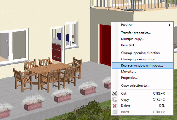 Now, planning balconies, terraces, and other areas where doors and windows are combined is even easier and more professional. Thanks to the innovative feature that allows you to replace doors directly with window constructions, you save valuable time and achieve perfect results in the 3D visualization.
Instead of laboriously deleting a door, navigating through the catalog, and manually inserting a suitable window, you can now simply select the door in your project and replace it with a window construction via the context menu—quickly, easily, and efficiently.
The advantages at a glance:
- Perfect 3D visualization: Window constructions are fully parametric, which means that frames and sash frames can be individually adjusted. In contrast, doors consist of finished 3D objects that often do not fit optimally with adjacent windows. With cadvilla, you can easily overcome this challenge.
- Professional floor plan representation: Even when using a window construction, you can mark door stops and opening directions in the floor plan with simple 2D symbols from the catalog. This keeps the floor plan clear and professional, while the 3D view is perfectly coordinated.
- Flexibility and time savings: This feature is ideal for anyone who wants to adapt their planning flexibly without losing time. Whether you work with window constructions from the start or make changes later—cadvilla makes it possible.
The properties dialog for 3D objects has been expanded with several new functions. This gives you an even more efficient and user-friendly way to optimize your designs. The new features not only save time but also make your work more intuitive and flexible. Here are the highlights:
Easy Replacement of 3D Objects
Forget the previous, time-consuming process of replacing existing 3D objects. Manually deleting objects, searching for new ones, scaling them, and repositioning them are now things of the past. With the new “Replace Object” feature included in the properties dialog, you can directly replace existing 3D objects with others—quickly, easily, and without any extra steps.
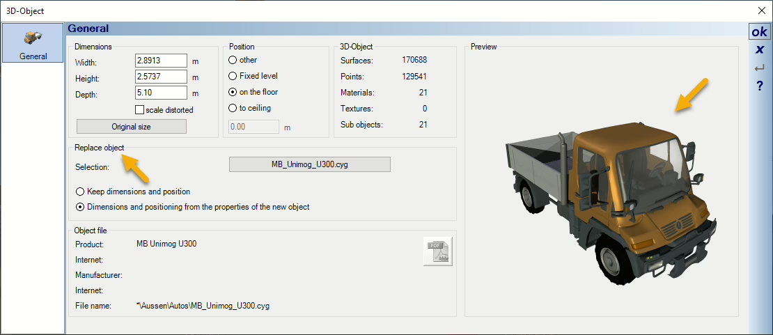 Flexibility with Dimensions: Decide whether the new object should keep its original size or adopt the dimensions of the existing object. This is especially useful if, for example, you have already scaled trees or other objects to the correct size.
- Seamless Integration: Simply select the new object from the catalog—and you’re done! The catalog accesses the currently set directory, so you can also work with your own objects.
3D Preview Directly in the Dialog Window
Thanks to the integrated 3D preview, you can now view objects directly in the properties dialog. This means you can immediately see what the object looks like without having to insert it into your design first. This saves valuable time and ensures greater precision.
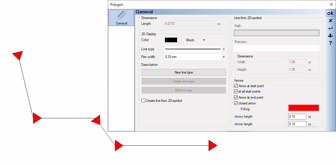 We have expanded the functions for lines and polylines to include arrow options. This allows you to implement your ideas even more precisely and professionally. Thanks to the new arrow options, you can now make your plans and drawings even clearer and more appealing.
You can now add arrows to lines and customize them entirely to your preferences. Decide where the arrows should appear along the line, how large they should be, and whether they should consist of two lines or have a filled appearance. This gives you maximum flexibility for your designs.
The start and end points of the arrows are automatically defined by the line itself—saving you time and ensuring precise results.
When using polylines, you can optionally add arrows automatically at every click point. This feature is ideal for clearly and understandably illustrating complex paths or directions.
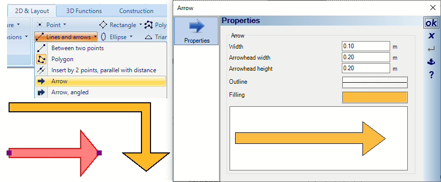 From now on, arrows are available not only as an addition to lines but also as an independent drawing element.
Use them to make your plans and layouts even clearer and more organized. The standalone arrows are perfect for precise markings and highlights in 2D top views. The input functions are intuitively accessible via the Lines and Arrows button in the 2D & Layout ribbon, allowing you to get started quickly and easily.
Each arrow has its own properties dialog, enabling you to adjust it precisely to your requirements.
Maximum control: Arrows are registered as their own element in the view visibilities. This means you can show or hide them at any time, as needed.
 Rectangles are now also available with rounded corners! Thanks to the innovative feature for creating rectangles with rounded corners, completely new possibilities are opening up for you – both in 2D and 3D.
- Customizable: Round all corners evenly or design individual corners according to your preferences. This way, you retain full control over the design.
- Finest details: Specify the number of segments to adjust the rounding precisely to your requirements. Perfect for detailed and professional results.
In 3D, rectangles with rounded corners can be used for modeling 3D objects! To do this, first save the entered rectangle as a 2D symbol. Then, insert the 2D symbol again and use the context menu to break it down into individual objects. This then serves as the basis for an extrusion body or sweep body.
With this new feature, cadvilla offers you the perfect combination of flexibility, precision, and efficiency. Whether you are working on a 2D design or creating complex 3D models – the rounded rectangles make your work easier and your drawings more professional.
So far, it has often been difficult to position windows and doors precisely in walls, as the walls would cover the underlying floor plan (inserted as an image). With the new feature, the wall becomes transparent while moving or inserting windows and doors. This allows you to clearly see the underlying floor plan and work with precision.
Your benefits:
- Maximum clarity during editing.
- Precise positioning of windows and doors without obstructive overlays.
- Time savings thanks to intuitive and visual support.

Placing floor plan images has previously been a challenge, as they would cover the already constructed walls. Now, the floor plan image becomes invisible while being moved, allowing you to clearly see the walls underneath. This enables precise alignment of the image with the desired points in your design.
Your benefits:
- Precise placement of floor plan images without obstructive overlays.
- Easy work with reference points for exact alignment.
- Improved efficiency in planning and editing.

In our example image, the floor plan is attached to the cursor. The position of the cursor is indicated by the yellow circle with a crosshair. The cursor should now be placed on the green X (target point), thereby moving the floor plan. With the new function, this is a breeze.
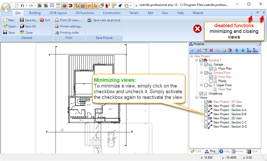
In cadvilla, minimized views are not updated automatically for technical reasons related to Windows. Until now, this could result in a minimized view appearing empty when inserted into a plan compilation. To ensure an even smoother workflow, we have now generally disabled the function for minimizing view windows. If you do not need a particular view, you can simply hide it by removing the checkmark in front of the respective view.
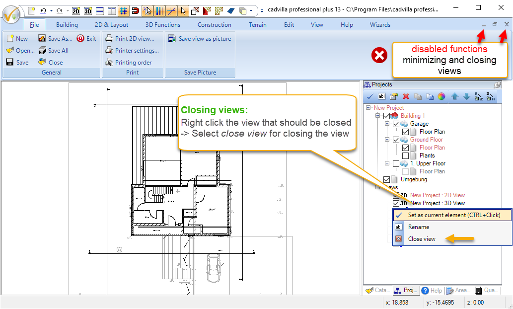
From now on, the behavior when closing 2D and 3D views in cadvilla has been made more consistent. When clicking the X, as with section views, the checkmark in front of the respective view is now simply removed for 2D and 3D views as well. If you want to completely remove a view, you can still do so easily via the context menu using the “Close view” option.
Your advantage: This prevents views from being closed accidentally, and the settings for visibilities and active layers are retained.
Additional features of cadvilla Version 2 – Version 13
Additional features of cadvilla Version 2 – cadvilla Version 5 are listed here.
Additional features of cadvilla Version 6 – cadvilla Version 9 are listed here.
Additional features of cadvilla Version 10 – cadvilla Version 12 are listed here.
Additional features of cadvilla Version 13 are listed here.