


Additional features of cadvilla version 9
The additional features of cadvilla V9 listed in the following table only represent the most important changes compared to cadvilla V8. Of course, many other smaller modifications and enhancements as well as the elimination of certain weak points, have also been implemented.
Legend for the following table:
![]() ,
,![]() – Feature is included in this version
– Feature is included in this version
![]() ,
,![]() – Feature is not included in this version
– Feature is not included in this version
Contrary to what is likely expected, groups are not just a combination of already existing 3D objects from the catalog, but mini-projects that can contain almost all constructive elements, but of course also combined with 3D objects. The constructive elements include walls, roofs, windows and doors, stairs, extrude solids, sweep solids and much more.
Groups are inserted in your project as usual via drag and drop from the group catalog.
The special thing about it is that groups can be separated into their previous elements once added to your current project. That means walls, windows and doors, roofs, 3D constructions, etc., simply all parts of a group become the original elements again and can be edited and changed as usual.
Please note: for editing and modifying the construction elements of a group the required function must always be available in your software variant. In particular, various 3D constructions (such as sweep solids, extrude solids, rotate solids) are included in many groups. These elements can only be edited with cadvilla professional versions or higher, since the 3D construction functions are only available in cadvilla professional or professional plus.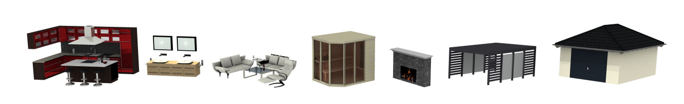
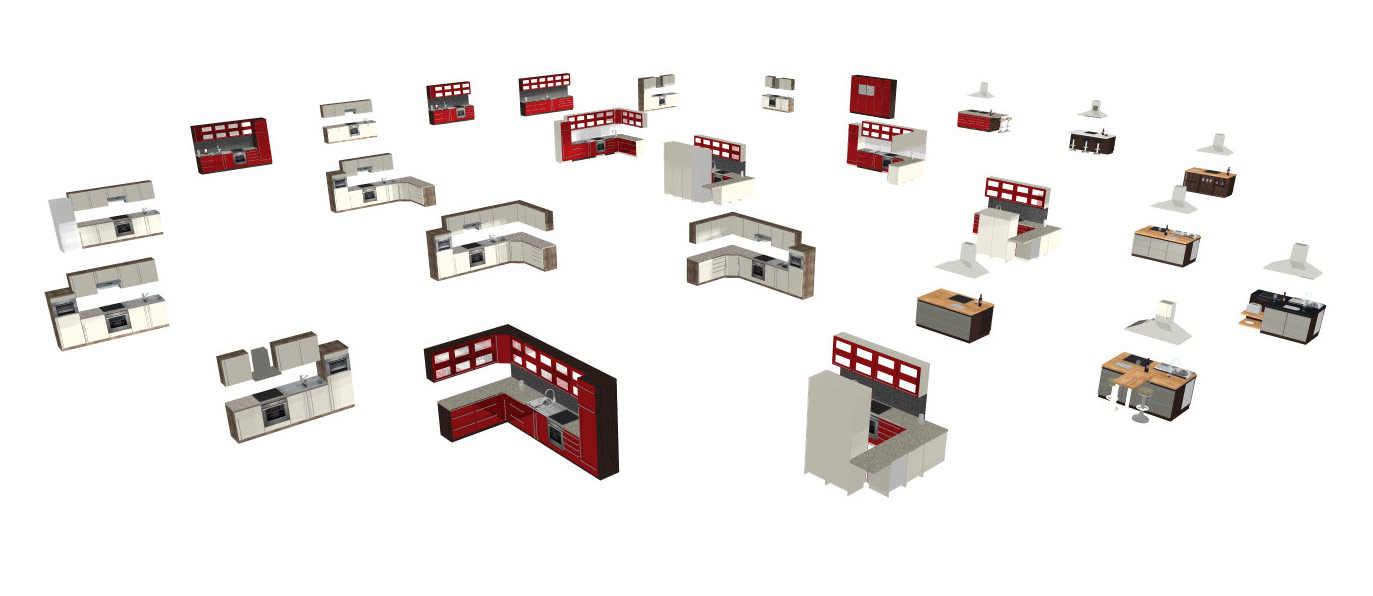
With our new groups, a completely arranged kitchenette or kitchen island is quickly placed in your floor plan via drag-and-drop. If the kitchen doesn’t fit right away, it can be adjusted with just a few clicks.
Separate the kitchen into individual elements and change these elements according to your wishes.
To do this, for example, remove a base cabinet from the kitchenette and replace it with another base cabinet with a different drawer combination. Or change the shape of the kitchen top with just a few clicks, reposition the refrigerator or replace the textures of your kitchen elements according to your ideas.
For more details please watch our video “Separating and editing of a kitchen group”.
¹) Please note that some kitchenettes and kitchen islands might also contain 3D constructions. These can be shown in all cadvilla versions, but can only be edited in cadvilla professional or higher.
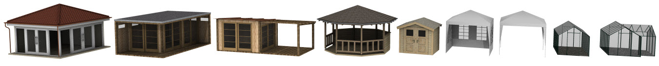
Would you like to place a pavilion, a garden home or a greenhouse in your garden and cannot find one that exactly matches your requirements? The new groups in cadvilla are the solution for this problem. Simply take an existing, similar looking group object from the group catalog and change it with just a few clicks according to your needs.
As a first step, drag the group object into your floor plan and then separate it into its original elements. Now you can select each individual element and change it according to your needs. For example, select an existing window and change the profiles, bar arrangements and dimensions in the window dialog, or change the roof pitch and cladding of the roof.
²) Please note that some greenhouses and garden homes might also contain 3D constructions. These can be shown in all cadvilla versions, but can only be edited in cadvilla professional or higher.
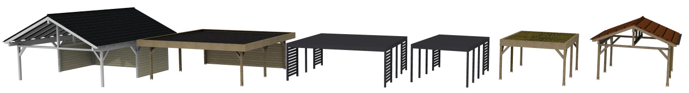
Planning your own, individual carport is just a few clicks away with our new groups. As a first step, choose a carport from the group catalog that best matches your ideas. Then drag and drop it into your planning and separate it into its individual elements.
Now comes the big advantage of our new groups. All carports contain various construction elements, such as roofs or 3D construction solids. By simply selecting the constructive element and then editing it in the dialog, you can change the carport according to your ideas in the shortest possible time.
³) Please note that all carports groups contain 3D construction elements. 3D constructions can be displayed with cadvilla basic and cadvilla basic plus, but changes in dimensions and shape are only possible with cadvilla professional or higher.
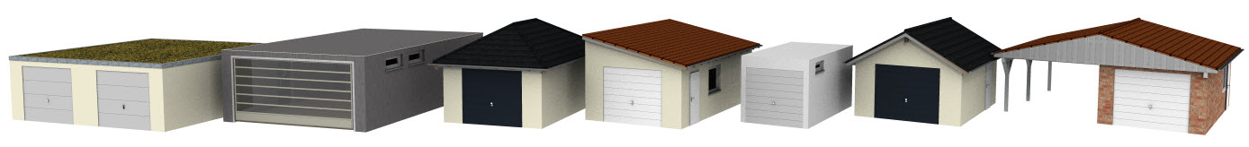
Are you planning to build a new garage, still looking for some new ideas, and would you like to realise them individually? The garages in our new cadvilla groups are ideally suited for this. The group catalog contains various double garages, single garages with different roof shapes or flat roofs and some combinations of garage and carport.
For individual adaptation, simply drag the desired garage into your project and then separate it into its individual elements. Now you have access to all further settings of the elements contained therein. For example, you can now turn a hipped roof into a sloping roof, edit and move windows and doors, delete or replace other elements or simply select a different garage door.
⁴) Please note that 3D constructions have been used in several garages. These can be shown in all cadvilla versions, but can only be edited with cadvilla professional or higher.
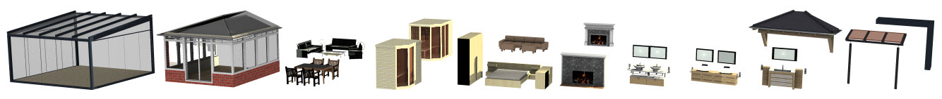
In addition to the groups already mentioned, the catalog contains others from the following categories:
- Bay windows
- Awnings
- various porch roofs and roofs for the entrance area
- modern conservatories and “British style” samples
- Bathroom furnishings and complete bath rooms
- Bedroom, living room, seating groups and fireplaces
- various sauna combinations
⁵) Please note that some groups listed above also contain 3D constructions. All groups can be used and displayed in all cadvilla versions. However, the 3D constructions contained in some groups can only be edited and modified with cadvilla professional or higher.
 Create your own groups in just a few steps and save them in your own group catalog.
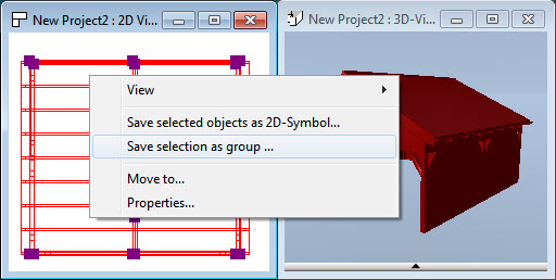
As first step, switch to an active 2D view and select all elements that should be included in the group. The easiest way to do this is to draw a frame around the individual elements while keeping the left mouse button pressed.
To save the group, press the right mouse button in the 2D view and select the option “Save selection as a group” from the context menu.
This step ensures that in addition to the individual group elements, the current 2D representation of the group is also saved at the same time. When you insert your own group later in a new project, the correct 2D representation is automatically used in 2D top views.
In version 9 we have added more than 1.250 new 3D objects from various categories.
So far, our catalogs have always pointed to the specified main directories in the cadvilla program directory. Loading your own 2D symbols and 3D objects from other folders was only possible via the “File open…” dialog.
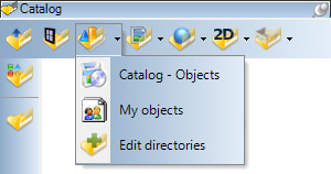 We have now expanded the possibilities here. As soon as you click on the arrow on the right side of a category button, a selection of the catalog folders appears. The default setting is:
- the standard catalog in the installation directory of cadvilla
- the predefined catalog in your users document folder
After selecting a new category folder, it is automatically displayed as usual in our catalog toolbox and therefore allows a better overview and handling of your own 3D objects, textures, materials, 2D symbols and now also for groups.
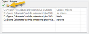 After clicking on the menu item “Edit directory” a dialog window appears in which further directories with your own catalogs can be added. This applies to all categories (3D objects, 2D symbols, groups, textures, materials). To add a new directory, click on the “New Directory” folder icon above the respective category. The next steps are standard Windows functions.
Our standard catalogs and the catalogs in your own user directory are grayed out and cannot be changed.
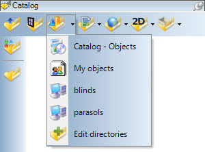 After the new directories have been defined, they automatically appear in the button menu. In our example, these are your own 3D object collections with blinds and parasols.
If you have several computers on which cadvilla is installed, the settings for the category directories can be transferred easily by copying the “UserPaths.xml” file.
For future updates, this file can also be copied into the new cadvilla user directory so you do not have to make the same settings every time from scratch.
 Until now, roller shutters could only be inserted manually using a 3D construction or simple 3D object from the catalog. Now the property dialogs for windows, window constructions and doors have been extensively expanded. In these dialogs you now find the option to add roller shutters automatically in the “Additional components” area.
We differentiated between the types
- Built-in roller shutters
- Built-on roller shutter (Front-mounted)
The height, depth and offset of the depth within the wall are also defined for each roller shutter.
For the 3D representation of the roller shutters, there is a large selection for both roller shutter types. You can choose between opened roller shutters and roller shutters in which the slats with different heights are included and visible.
The picture on the right shows an example of the dialog for window constructions.
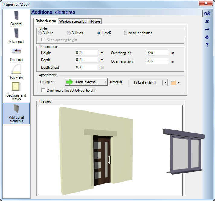 In the past, drawing and displaying lintels for windows and doors could only be done manually. Now we have added a much more comfortable solution.
Similar to the roller shutter, lintels for window constructions, windows and doors are activated on the “Additional components” page.
The height, depth, depths offset and the overhang left and right for the lintel can be edited.
The picture on the right shows an example of the dialog for doors.
 So far, it has always been the case that surroundings for windows and doors could only be achieved with the help of individual 3D surfaces attached to the outer wall.
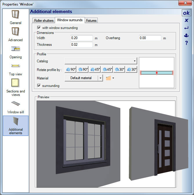
In our new dialogs for windows, window constructions and doors there is now a separate area in which Window surrounds can be defined.
The width and the thickness of the element can be edited.
Another option specifies whether the surrounding should end at the window sill or the threshold (e.g. for floor-to-ceiling windows and doors) or should go around the entire window.
The picture on the right shows an example of the window dialog.
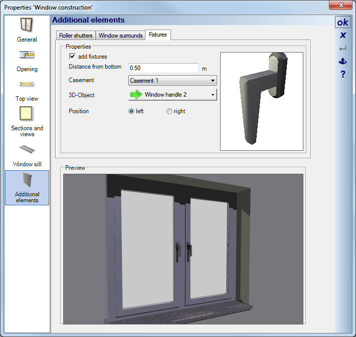 So far, the display of window handles in window designs was only possible by manually inserting handles from the catalog. This point has now been generally solved in the window constructions dialog.
In the dialog there is now a tab for “Fixtures” on the new “Additional components” page.
In this area, the position of the window handle can be determined for each sash of a single or multi-sash window. The distance from the lower end of the selected window sash and the position (left or right) can be changed.
The objects for the window handles themselves are normal 3D objects from the catalog. You could therefore also use other, identically rotated variants.
In the picture on the right you can see an example of a double window with newly defined window handles.
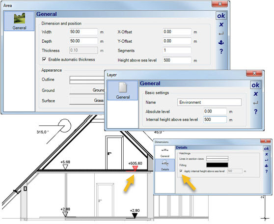 Height dimensions in sections and elevation views in cadvilla always refer to the zero level of your planning.
Optionally, you can now specify an internal value that is added to this level, an internal height above sea level. This internal value for the sea level can be set either in the dialog of the terrain or in the properties of the “Environment” layer.
The corresponding option for adding the sea level can then be activated in the Properties dialog of the height dimensions on the “Details” page.
The new help plugin has been implemented especially for beginners and new users. It is located in the general toolbox, where you can also find the catalogs and the project viewer.
Within the toolbox, various help topics are structured in a tree view and can be opened via the context menu on the right mouse button or by double-clicking.
Upgrade and switch to a larger version of cadvilla at the same time
You want to extend the scope of your version and upgrade to a larger version? Here you will find all possibilities.
Additional features of cadvilla version 8
The additional features of cadvilla V8 listed in the following table only represent the most important changes compared to cadvilla V7. Of course, many other smaller modifications and enhancements as well as the elimination of certain weak points, have also been implemented.
Legend for the following table:
![]() ,
,![]() – Feature is included in this version
– Feature is included in this version
![]() ,
,![]() – Feature is not included in this version
– Feature is not included in this version
 As of version 8, cadvilla enables you to enter walls in a timber frame design and essentially offers three different methods.
A)You set the properties of the timber stand layer already before or while entering the walls. Once the wall is integrated into the project, it automatically fills with timbers.
B)You simply open the properties dialog of existing walls and activate the timber construction for it.
C)You load a conventionally planned project and start the timber construction wizard to fill all walls of the project with timbers in one single operation.
 In addition to creating parameterized timbers, you can manually add vertical, horizontal or any other timbers in wall layers. The input is done in sectional views that you can create and work in with one mouse click.
The timber used for each wall but also for the entire project can be output as PDF, RTF or Excel files using our known output mechanisms. The output document contains tables with timber lists and a sketch of the wall, incl. standard dimensions that enable you to see the arrangement and position of the timbers.
 The terrain including the terrain elements can now be evaluated in a new dialog by area, volume and excavation.
The evaluation dialog shows a list of the bodies that project into the terrain and a corresponding 3D preview enabling you to also assign the elements visually.
Bodies include:
- The parts of existing buildings that reach below ground level
- Terrain elements such as paths etc. that include depth in their characteristics
- Foundations
- 3D subtraction solids allowing you to design the terrain or to, e.g., to create underground parking garage entrances
In the 3D view, the parts of the bodies that form an intersection with the terrain are marked in red while other protruding parts are marked in green. Additionally, the calculated values are displayed.
The dialog also offers you a table with information on all individual items which you can copy completely or partially for further calculations and paste, for example, into an Excel table.
 An additional dimensioning option now allows you to dimension windows and doors on axis via their properties dialog.
There are appropriate options for each. The dimensioning of doors within the element is displayed centrically while the dimensioning of windows is optionally displayed centrically from the opening direction.
As usual, you can transfer these properties to other elements in your planning using the function “Transfer properties…”
 Individual foundations, strip foundations and floor panels were added as new constructive elements.
The dialogues, properties and input mechanisms are similar to those of the known downstand/upstand beams or ceiling panels.
The new component types can be distinguished by strip foundation and foundation (incl. floor panel) and can be displayed specifically through their visibility and both appear in the mass evaluation as well as in the evaluation dialog of the terrain.
 Previously, 3D views could only be aligned via the normal navigation functions.
Now, cadvilla offers two simple basic functions via new buttons on the “display” ribbon. These functions enable you to take a viewer’s perspective directly above the building. This way, you gain a precise view from the top or views from the side while being able to move around the building via the new dialog with a few simple mouse clicks if required.
The functions put the active 2D view in a special mode allowing you to only use the functions required for navigation. In the top view, this would be rotating around the Z-axis and in the side views, this would be moving the view to the right/left and upwards/downwards. You can terminate this alignment mode by pressing the ESC key and then move around in 3D again as usual.
 Previously, doors were always closed in 3D, like in a 2D drawing. Now, you can open the doors in 3D, i.e., rotate them by an adjustable angle without changing the 2D drawing. Select a door and choose “Open door in 3D view” in the context menu. You can find the same function also in the properties dialog of the door.
This function enables you to, e.g. create 3D views from the top and to mark the stop and opening direction of the door.
 In response to many requests from our customers, we have extended the catalogue of 3D objects by numerous window shutters for all common window formats.
The variety of combinations also creates numerous objects. Another benefit is that a suitable 3D object is available for practically any window size without the need to scale and distort the objects which often leads to unrealistic presentations.
 We also extended the choice of blinds in our 3D objects catalogue accordingly for all common window formats.
This also results in numerous 3D objects. Corresponding blinds are included for all common window dimensions. Scaling is no longer necessary and the associated partly unreal presentation is a thing of the past.
For blinds, there are even various heights for each width available. This allows you to equip your building with objects in almost any opening state just like in reality.
 In addition to already existing 3D objects, further 3D sliding shutters and modern 3D radiators were added.
The function allows you to measure a polygon and to immediately place the measured area as standard text.
Previously, windows and doors were always shifted proportionally if the wall length was modified. This should prevent you from shortening walls in a way that windows and doors were no longer present inside this wall.
We have improved this behavior. When extending and shortening walls, the elements contained in them maintain their exact position. If the shortening results in a window or door being located outside the wall, a dialog box appears where you can define this behavior. Optionally, you can delete the element or even keep it in the wall.
In any case, you no longer have to reposition the elements each time you make a change (using the CTRL-V function).
 The known terrain elements such as paths, beds, terraces etc. now feature a number of additional possibilities.
- Editing polygon points in 2D and 3D
- Changing the contour by adding or removing polygon points
- Entering a value for the height above the terrain, i.e. elements protrude from the terrain
- Entering a value for the depth in the terrain to determine the required excavation
- Entering a logical name for the elements so that they can be identified in the new evaluation dialogs
Additional features of cadvilla version 7
Below, you can find additional features of cadvilla Version 7 compared to cadvilla Version 6
Legend for the following table:
![]() ,
,![]() – Feature is included in this version
– Feature is included in this version
![]() ,
,![]() – Feature is not included in this version
– Feature is not included in this version
 Initially, five different line types were available in cadvilla. Now, you can also define your own line types. The standard line types were supplemented by 14 additional pre-defined line types which you can now extend by your own individual line types.
When creating your own lines, you can piece them together from individual segments. For this, just define the line length and the distance to the next line per segment. Then, assign a description for the line type and save the new definition with OK in the line definition file in the user directory. The newly defined lines are automatically available in all line dialogs.
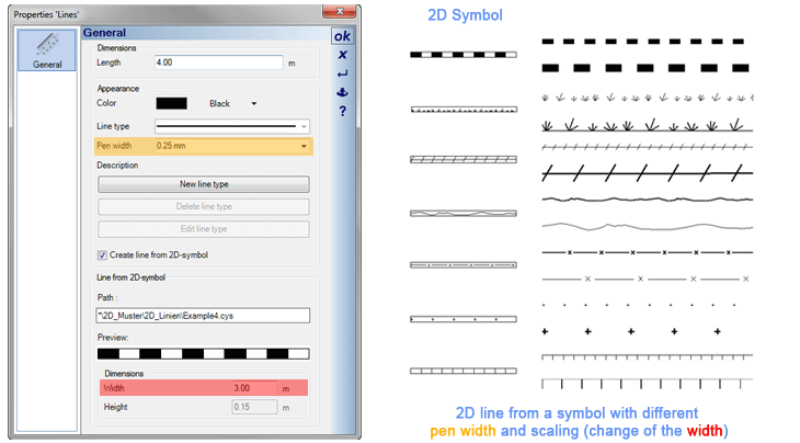 Similar to free hatchings, you can now draw a segment of your own line and file it in the symbol catalog as a 2D symbol for further use.
A 2D line from 2D symbols is a line where a selected 2D symbol is ordered in sequence. To create an own line, first draw a segment of the line – surrounded by a rectangle – using the 2D drawing functions such as lines, polygons, circles etc. Then, save this line section as a 2D symbol.
When drawing the line from 2D symbols, assign the 2D symbol to the line in the line dialog. The surrounding rectangle from the symbol is removed and the remaining content is ordered in sequence along the curve (tiled).
There is an area in the line dialog called “Dimensions”. In case the symbol length changes, the height changes proportionally and thus enables a scaling of the symbols on the line.
Please find some examples of line types in the 2D symbol catalog under “Graphics 2D/2D Sample/2D Lines”.
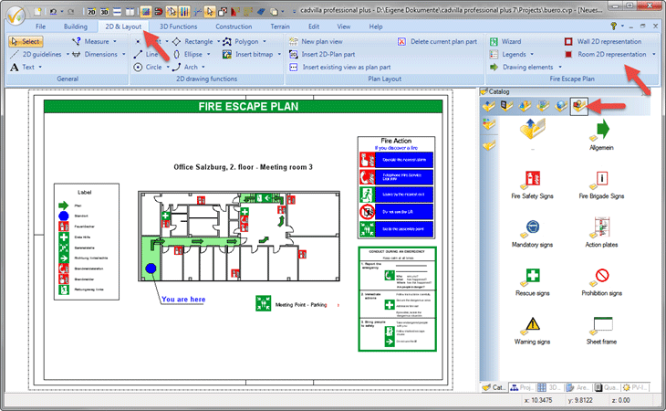 Creating escape and emergency routes as well as firefighting plans according to DIN EN ISO 7010; DIN 4844-2 and DIN 14034-6 becomes tremendously easy when using the new escape and emergency routes planner.
Prior to creating the escape and emergency routes, a floor plan fully completed in cadvilla is required. If you already have such a project, you can immediately start planning escape and emergency routes. Otherwise, first create a floor plan with the functions available in cadvilla to enter walls, windows, doors, stairs and all other elements which should also be shown in the desired planning documents.
The following functions are available for planning escape and emergency routes:
- Wizard to create an escape and emergency routes plan view:The wizard generates the floor plan in a new 2D view and in the correct scale. It assists you in placing a corresponding drawing frame. A special 2D view is automatically generated with the defined settings, and the floor plan is inserted with a frame.
- Drawing functions for arrows and for marking the location
- Simple color marking of walls and rooms
- Comprehensive catalog with all required 2D symbols (standardized elements) to plan escape and emergency routes
- Automatic generation of legends by means of the placed 2D symbols or from pre-defined templates
You can buy our fire escape planner also as an extra add on to your cadvilla version. Further information and how to use our fire escape planner you can find in our guides.
 By default, buildings and layers in the project tree are presented in the same order as they were generated. With this function, the order of layers can be changed within each individual floor, and the order of buildings as well.
It is possible to change the sequence manually and alphabetically ascending and descending. The order of layers can be sorted separately for each individual floor. A manual change of the sequence in the project tree is possible as well.
 In the first step, own categories are created via the context menu in the project viewer.
Afterwards, you can assign already created views to these categories. Especially in case of many views, this function allows you to maintain an overview of the project.
By activating and deactivating the categories, the included views are automatically switched to visible or invisible.
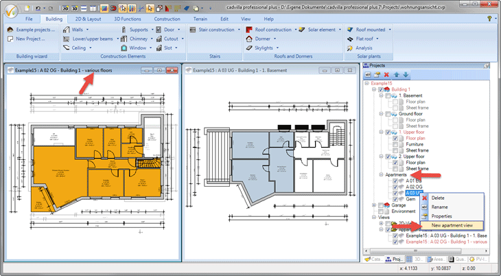 When designing a new apartment via the context menu of the building, a new hierarchy level occurs called “Apartment”. The newly designed apartment is classified in this hierarchy level. Afterwards, this apartment can be assigned to rooms that have already been created.
Via the context menu of the apartment, an apartment view can automatically be created which displays all rooms of the apartment in color. The color of the spatial representation can be selected in the properties of the respective apartment.
In the apartment view, only those floors are automatically switched to invisible where there are assigned rooms. If the rooms of the apartment are distributed across several floors, the note “different floors” occurs also in the title of the apartment view.
 The visibility templates allow you to generate templates for various combinations of visibilities according to your own ideas.
Beforehand, create a visibility template that you need for your daily work, assign a name to them and save them universally. Afterwards, visibility templates (similar to a stencil) can be linked with views for existing projects that have already been created.
This way, the pre-defined visibilities can be transferred with just one click from the template to the views.
This eliminates the need of manually setting the combination of visibilities for individual views.
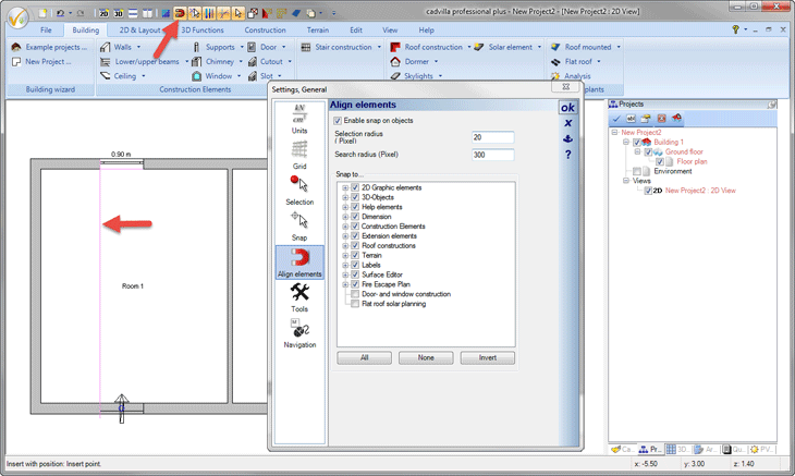 In addition to the previous snap mode, the alignment of edges included in the project has been introduced for placing elements.
After activating the ‘Alignment mode” via the upper toolbar placing or shifting elements, the program searches for appropriate edges formed by existing objects. These edges are automatically extended towards the element to be positioned, and thus enables an exact placement of this temporary edge line through snapping.
This way, an element can exactly be aligned to another element without working with auxiliary lines or other design aids as before. The radius, in which the system searches for existing edges, can be adjusted in the general settings.
This input assistance works with all elements. This way, e.g. texts can be aligned to each other, or also doors and windows to opposite elements.
After selecting a dormer, it can be shifted accordingly using the shift functions. Dormers can be copied via the key combination Ctrl-C – and reinserted, also into another roof side, using the key combination Ctrl-V.
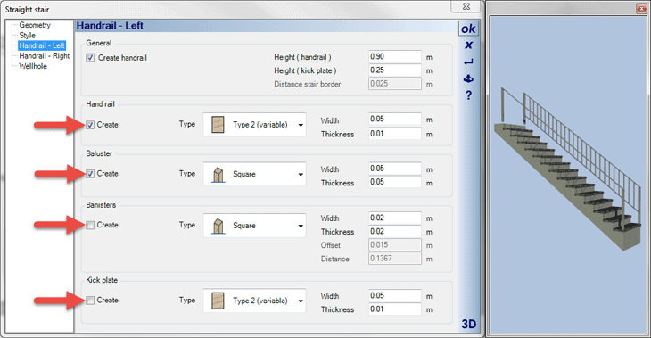 Besides the optional representation of a stair railing, now components of a railing can also be activated or deactivated separately. This option is available for the handrail, the posts, the pickets and the foot rail.
In our example, the pickets and foot rail were deactivated for the left railing.
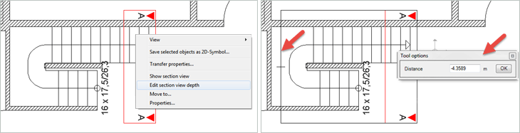 So far, the depth of a cut has only been specified when entering a new sectional view and could not be changed later on.
If a change of the cutting depth was required later on, a new cut had to be created without exception. However, the disadvantage of this was that changes in the cut, such as additions and dimensionings, could not automatically be adapted meaning that the sectional view with the changed cutting depth had to be re-entered.
The new function allows you to change the cutting depth in the context menu after selecting the existing cut symbol. And the sectional view including all additions and changes is maintained. Only the cut itself is recalculated in the sectional view.
So far, polygon corner points of the roof could only be shifted.
Now, polygon corner points can also be deleted after they have been selected, and other points can be added via the context menu.
The roof side properties can be reset to standard values and the roof behaves as if it was newly entered.
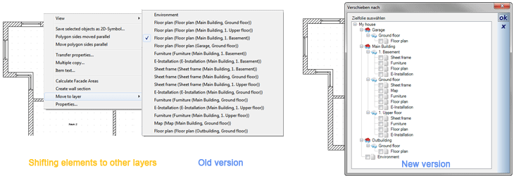 Elements could so far be shifted to other layers via the context menu. To specify the target layer, another context menu was opened in which all available layers were listed one below the other. However, this method quickly became confusing and unclear in case of larger projects and large number of layers.
Now, a dialog window appears for specifying the target layer in which you can specify the target via a project tree, similar to the tree in the project viewer.
The DXF/DWG import and export also support the new 2018 formats.
Furthermore, the import was improved in many ways as well. E.g., in the past it could happen that the dimension lines reached up to the dimensioned element. This has been changed so that such dimension lines obtain our standard settings and can thus provide a better visual presentation.
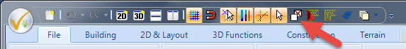 There is a button in the toolbar to rapidly switch ceilings on and off.
Now, when shifting with the pressed mouse button (within the plan parts), the position is maintained after the project is called up and even during printing.
Auxiliary lines are always located in the foreground and are not overlapped by selected objects.
The boxes surrounding a text can now be used as a snap point.
Longer texts on the screen now correspond to the print display.
For cadvilla professional and professional plus:
Corrections in case of subtraction solids and the elements to be considered here.
Additional features of cadvilla version 6
Below, you can find additional features of cadvilla Version 6 compared to cadvilla Version 5
Legend for the following table:
![]() ,
,![]() – Feature is included in this version
– Feature is included in this version
![]() ,
,![]() – Feature is not included in this version
– Feature is not included in this version
 There are two tools for mirroring 2D symbols that appear in the selection tool bar once a 2D graphic symbol has been selected. Mirroring a 2D symbol can be done on any specified axis or at the center point of the 2D symbol.
A distinction is made between two types of mirroring
- Basic mirroring
- Mirroring with a copy. In case of mirroring with a copy, the initial element is preserved and a new, mirrored 2D symbol will be created.
Mirroring still works even after selecting multiple 2D graphic symbols. After specifying the type of mirroring, all selected 2D graphic symbols will be mirrored at the same time.
 Mirroring a 3D object can be done at the center point of the 3D object or on a defined mirror axis.
After selecting a 3D object, there are two mirroring tools available in the selection toolbar.
- Basic mirroring of a 3D object
- Obtaining a selected 3D object and creating a new, mirrored 3D object on the mirror axis.
Mirroring works even after selecting multiple 3D graphic symbols. Select multiple 3D objects and determine the type of mirroring in the selection toolbar. Afterwards, all selected 3D objects will be mirrored in one step.
 As of version 6, there are 380 new 2D graphic symbols from the areas electronics, gas, water, safety technology available.
 The texture catalog with more than 350 textures made by mtextur from the areas of asphalt, concrete, wood, HPL, ceramics, gravel, brick, plastics, metal, nature, natural stone, parquet, cobblestone, plaster, stone basket, flagstones, carpet, terrazzo
The example shows an image taken using cadvilla with textures from the areas of concrete, plaster, wood, concrete, natural stone, ceramics, gravel, asphalt, terrazzo, cobblestone, metal mesh.
 As of version 6, you can load other 3D formats into cadvilla in addition to the existing 3D formats, edit them right there and then save them as a cadvilla object file.
Besides the most known new 3D formats Google SketchUp and Collada, many other 3D formats can be used with cadvilla.
In detail, these additional new 3D formats are the following file names:
- Google SketchUp (*.skp)
- Collada (*.dae)
- Autodesk FBX (*.fbx)
- Luxology Modo (*.lxo)
- Polygon file format (*.ply)
- Stereolithography (*.stl)
- VRML 2.0 (*.wrl, *.wrl97, *.vrml)
- DirectX (*.x)
In case you want to save specific parts of your projects as a 3D object, you can now export to one of the above mentioned 3D formats (apart from the existing 3D formats).
This option is interesting, for example, if you want to exchange data with a partner participating in your project. You simply have to agree with him on a suitable 3D file format, and your partner will be able to display the file sent to him in his own 3D program.
Especially when it comes to the 3D file formats Google SketchUp or Collada, most online portals provide access to a huge variety of up-to-date 3D objects. The majority of IKEA’s product range is, for example, available in Google SketchUp file format. On portals like 3D Warehouse , you can search for the desired objects through a search function, download them and import them in cadvilla. The use of the portal is subject of the terms of use from 3D Warehouse
The demonstration objects displayed here have been loaded from 3D Warehouse and then imported in cadvilla. The use is subject to the license terms of 3D Warehouse.
The new 3D important options and an internet connection allow you to access millions of 3D objects.
 As of version 6, it’s possible to enter roof-mounting photovoltaic systems into the system. Capturing photovoltaic systems (in short: PV systems) is supported by an easy-to-use input mechanism while allowing for planning of a complete PV system within just a few minutes.
When entering the PV system, select the desired PV modules from a catalog and determine the associated parameters such as e.g. lateral spacing. In the distribution of the modules, all parameters will have an impact on the respective roof surface. When entering the data, the allocation of the module on the selected roof surface will be displayed.
After the confirmation of the proposed distribution of the PV modules with one mouse-click, the PV system will be inserted in the planning.
Now you can roughly calculate the output of the PV system via the evaluation dialog. In addition, you can obtain a parts list of the used modules with its mounting materials via the dialog based on neutral assumptions. These parts lists can then be exported and printed as an Excel, PDF or RTF document.
In case the prices for the PV module and its mounting units in the dialog are preset by the user, a rough cost calculation can be done as well.
 In case of flat roof systems, you should determine the placing regions first. Placing regions are areas where the PV modules can be placed. Within these placing regions you can define the areas in which no PV modules must be installed.
After determining the placing regions, place the entire PV system with two mouse-clicks by simply determining the starting point of the placing using the mouse.
Afterwards, you can finalize the planning process using functions for modifying the row spacing, rotating the system (manual alignment of the modules and rows) as well as for setting a manual starting point.
 The new function “3D raster elements” in the section “Surface planner” serves the purpose of covering surfaces (e.g. walls, floors) that should be covered with 3D elements in an evenly distributed manner as rows and columns.
Typical application areas for the function “3D raster elements” are for example facade claddings, mirror tiles, representation of floor plates in the outdoor area, wood panels, thermal insulation and many more. With just a few mouse-clicks individual walls up to entire building facades are veneered with 3D surfaces, or its terrace surface are covered with timber floor boards.
Openings in walls (e.g. window and door openings) are considered and can automatically be left out. The remaining surfaces arising from this are automatically added by partial surfaces from the 3D elements.
Profiles for the installation of the 3D elements can be created additionally and can automatically be inserted between the rows and columns. The cross-section of the profiles is selected from a pre-defined catalog or can be created on your own as well.
The created 3D surfaces can be provided individually with different textures and materials, but also in separate columns or rows.
Each included 3D element can be further divided into sub-surfaces with different dimensions and can manage its own materials.
After selecting a placing area in the 3D area of the 3D raster elements, you will receive a parts list of the placed 3D elements with the respective measurements. Identical 3D elements are added up in terms of their number and are summarized.
 After the selection of an exterior wall, the context menu provides the function “Determine facade surface”.
When using this function, the software automatically identifies all exterior walls that are located exactly above and below of the selected wall and combines those to a total surface area.
This wall surface is then displayed in the following windows with a symbolic facade image. Wall openings (window and door openings) can be considered completely when determining the surface. But it’s also possible that the wall openings are only subtracted for a definable subtraction area higher than x.
 The list for the facade areas is created by a document that represents all facade surfaces of a building using a graphic for a facade view, the lengths and the width of the facade, and the gross and net surfaces (total surface area minus openings).
This list can be put out in PDF, EXCEL, HTML or RTF format.
 The list for the roof surfaces includes all roofs of the building with graphics and a table including the total values for the roof surfaces, the ridge length, collar length, verge length, and gutter length.
At the end of the list of roof floor spaces the individual lengths and surfaces of all the roofs used in the project are summarized.
This list can be put out in PDF, EXCEL, HTML or RTF format.
 The list for 3D raster elements is created by a document that represents the associated individual raster elements for all the previously selected raster surfaces in the form of a graphic, the number of equal elements, the description and the measurements. This list can be saved in PDF, EXCEL, HTML or RTF.
 The evaluation of the list for all windows contained in the project includes a representation of all windows with dimensioning and representation of the set swinging/tilting definition.
In the table mentioned below the outer dimensions, the used materials (including remarks) and the total number of each window type is included.
This list can be put out in PDF, EXCEL, HTML or RTF format.
- List of all floor spaces:
The list of all floor spaces of the building includes a list of all rooms for all floors levels with the associated floor spaces and the total surface area of the rooms of the floor level.
This list is, e.g., aimed at enabling flooring technicians to quickly determine how many square meters of parquet or carpets will be required.
- List of all wall surfaces and ceiling surfaces:
The list of wall and ceiling surfaces includes a floor-wise list of rooms with associated sidewalls and information about their lengths, heights and space.
The ceiling surface of the room is put out in addition to the room description.
This list is, e.g., for paintwork in order to be able to quickly determine how much paint will be required.
Both lists can be put out in PDF, EXCEL, HTML or RTF format.
 After selecting a 2D symbol, the following parameters can be changed for the entire symbol in properties dialog.
– The line properties including color, line style and line width
– The filling properties of filled surfaces of the 2D symbol
This functions allows you to quickly color-adjust 2D symbols afterwards in the 2D view. For example, all electro symbols will change to gray and all water installation symbols will change to blue.
Another application option of this function would be the colored representation of the demolition and new construction of a project.
The process would be as follows:
- Select the areas for the demolition in the 2D view and save them as a 2D symbol.
- Select the areas for the new construction in the 2D view and save them as a 2D symbol.
- Insert both 2D symbols in the view, place them in the foreground and color them as desired.
- Afterwards, maybe disintegrate the symbol and delete parts of it.
- Zooming on the cursor position has been assigned to the mouse wheel.
- Shifting up/down has been assigned to the hot key CTRL+SHIFT+mouse wheel.
(Both functions can be changed back to the default settings of the previous versions via the settings menu) - Viewer’s standpoints can now be deleted more easily with new buttons via “3D functions ➤ Viewer’s standpoint ➤ Delete viewer’s standpoint”.
- The selection of a room (room text) selects the associated room text (room). Another click selects only the object clicked on.
- After renaming slides, the slide name is updated everywhere.
- The pre-setting of the graphic format for “Save view as image” is now JPG.
- The numeric post-editing of polygons via the context menu.
- Surface planner: Surfaces can be edited in 3D: Add, delete points, and shift pages in parallel, shift polygon points.
Upgrade your cadvilla or switch to a larger version of cadvilla
Would you like to expand the scope of your cadvilla version and upgrade to the latest version? Or would you like to switch from your existing cadvilla version to a larger version of cadvilla right away?
Additional features of cadvilla Version 2 – Version 13
Additional features of cadvilla Version 2 – cadvilla Version 5 are listed here.
Additional features of cadvilla Version 6 – cadvilla Version 9 are listed here.
Additional features of cadvilla Version 10 – cadvilla Version 12 are listed here.
Additional features of cadvilla Version 13 are listed here.