Additional features of cadvilla version 12
The additional features of cadvilla V12 listed in the following table only represent the most important changes compared to cadvilla V11. Of course, many other smaller modifications and enhancements, as well as the elimination of certain weak points, have also been implemented.
Legend for the following table:
![]() ,
,![]() – Feature is included in this version
– Feature is included in this version
![]() ,
,![]() – Feature is not included in this version
– Feature is not included in this version
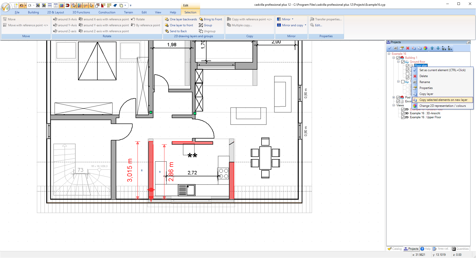
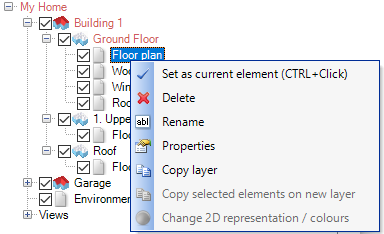 Usually, when the building is created, layers are duplicated by copying them in combination with the floors in which they were created. Now there are new functions for cases in which only one layer should be copied. You can find this in our right mouse button context menu when you click on a layer in our project viewer.
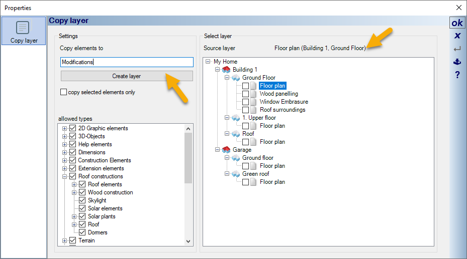
When planning new building elements or elements that are intended for demolition or conversion, it can be useful to copy layers . But also, for example, a layer with interior fittings that was only created at a later time can be copied to other floors afterwards.
Proceed as follows to highlight walls, windows, doors and stairs for demolition or conversion:
- In a first step, certain walls, windows, doors and stairs that are affected by demolition or conversion are placed on their own (new) layer within same floor. You can also duplicate an existing layer and then remove elements that are not required.
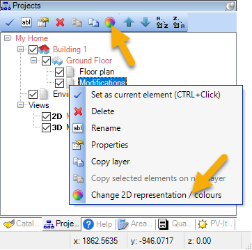
- After that, if you have an existing 2D view, select the selected layer with the right mouse button and go to “2D view, change colors”. Alternatively changing the colors within the selected layer can also be selected via the project viewer toolbar.
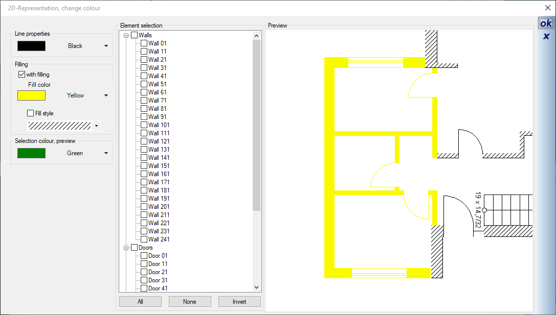
- The dialog for changing the line and fill properties of elements appears.
- By simply clicking on the wall, window, door and stair elements in our preview window, they are colored according to the specifications on the left. The settings can also be changed in between.
- Since the coloring of the elements is a temporary coloring (in contrast to the new dialog for permanently changing the fill properties of walls), the changes can be undone at any time. If coloring is no longer desired for an element, simply disable the checkbox from the element selection tree.
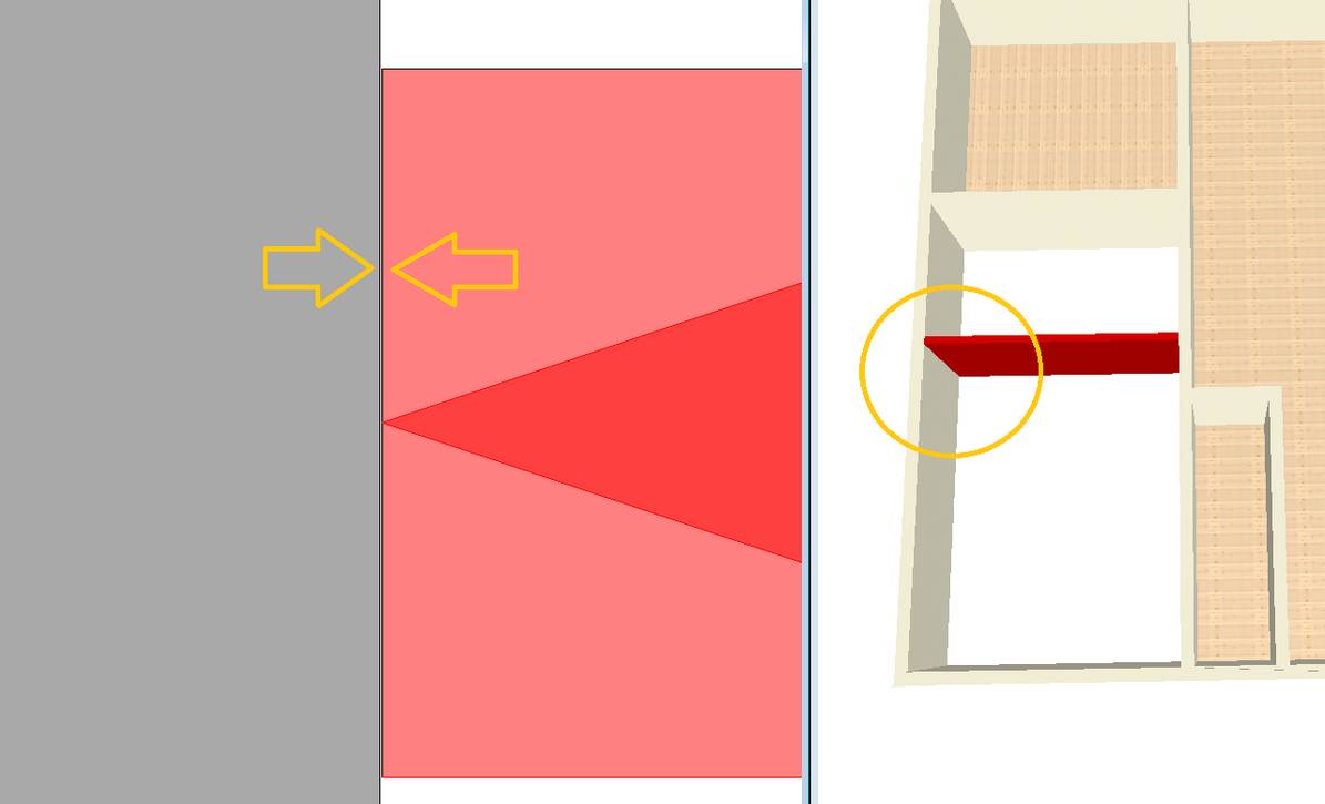
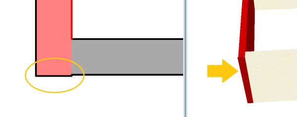
To display parts of a wall (as opposed to an entire wall) in a different color, in red, for example, and thus mark it for a special use case, proceed as follows:
- Select the walls to be changed (with the original lengths) and copy them to a new layer within the same floor using the context menu of the layer (Copy selection to new layer).
- In the context menu of the newly created layer, select the option “2D representation, change colors” and color the walls as desired.
- Change the individual lengths of the affected walls (e.g. by selecting the wall and changing the length, or with the shortcut V)
The result looks like this:
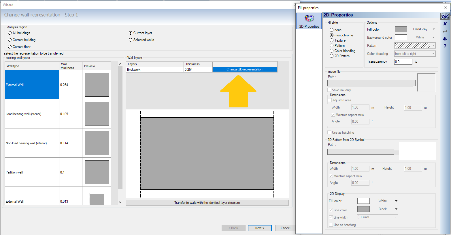
In contrast to the temporary coloring of walls (to highlight demolition or conversion walls), the new dialog under “Edit ⇾ Edit walls ⇾ Change 2D display” is for permanently changing the fill properties of walls in 2D views (plan views).
After starting the wizard, all walls with the same thickness and the same layer structure are listed. Two exterior walls with the same layer structure but different thicknesses are displayed as two different walls, for example.
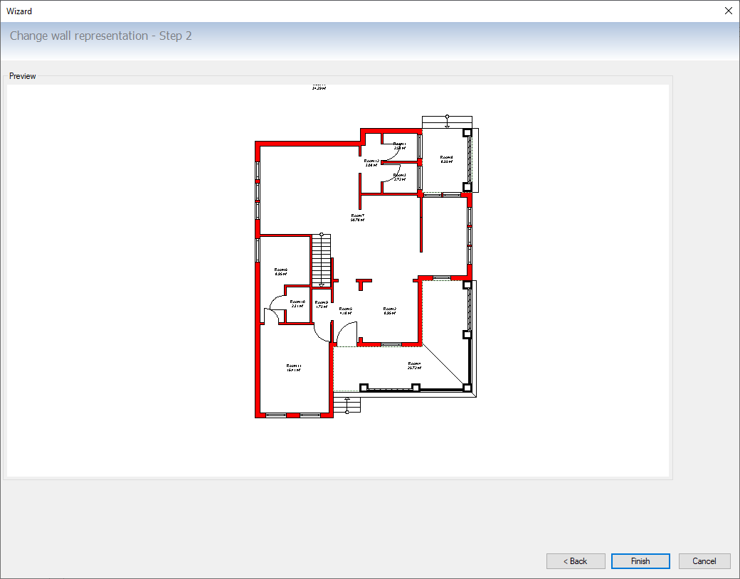
As soon as a listed wall has been selected, it is shown enlarged in the preview. A table appears above this preview showing the wall layers and the possibility of changing the 2D representation of each layer. After clicking on “Change 2D representation” the color representation of the selected layer can be specified in the subsequent fill properties dialog. In a next step you get a preview with all changes that only needs to be confirmed.
The new “Change wall layers” function is located in the “Edit ⇾ Edit walls” area. You first get a dialog with the wall types of your project. After selecting a wall type, a detailed representation of the wall structure and a table with the wall layers appear on the right-hand side. In the table you have the option of specifying one of the contained layers as fixed in its position (fix with the checkbox).

In the second part of the dialog, the layer structure of the wall type can then be changed as usual in our wall properties dialog.
New is that you can now specify whether the
- the position of a specific layer (fixed in the checkbox),
- the inside of the original wall (affects only outside walls)
- the outside of the original wall (affects only outside walls)
- the wall axis of the original wall
should be retained for the new layer structure.
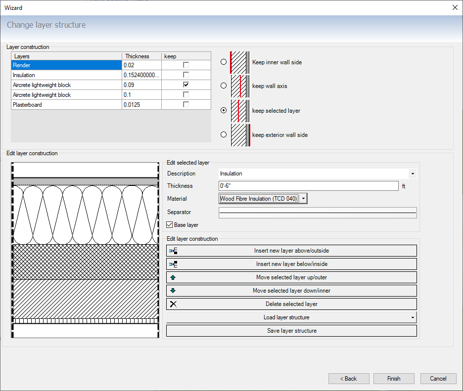
A typical use case for this feature is to quickly change exterior walls. An example: We have defined 32cm thick exterior walls as “masonry with insulating plaster”. These should now be changed to “masonry with insulating layer and plaster” with a total thickness of 42cm. The selected layer (the masonry) should not be changed in its original position. If you make the changes as shown in our screenshots above, this is done with a few clicks.
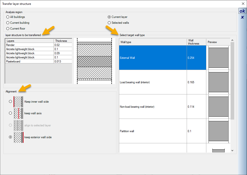
In our previous versions, it was already possible to transfer a layer structure. But it was not possible to determine which axis should be retained for the target wall (exterior, wall axis, inside).
Using the new wizard is of great advantage, especially when changes are made to exterior walls (e.g. addition of an insulation layer).
In the first step, the starting wall with the layer structure to be transferred is selected. This is done either by selecting the desired wall, or via a separate dialog under Edit ⇾ Edit walls ⇾ Transfer wall layer structure.
In a second step, the target walls are defined. What is new is the possibility of specifying the alignment of the layer structure to be transferred for the target wall. This is particularly important when the target wall becomes thinner or thicker due to the layer structure to be transferred. Alignment can specify whether the target wall should keep the inside, outside, or wall axis.
The definition of inside or outside only applies to exterior walls. For interior walls the only correct option is wall axis. Therefore, if the layer structure is changed, the positions of the inner walls may have to be corrected later in a further step.
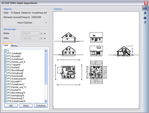
Drawing a preview of 2D DXF / DWG files to be imported in the dialog has been completely revised and is therefore significantly faster.
Until now, the preview was constantly updated when drawing individual elements and this took a lot of time, especially with large files. Now the preview behaves like in other dialogs with 2D preview and always draws the entire content, which is significantly faster.
 The floor plan analysis is a tool for quickly analysing the connections/intersections of walls within the floor plan and correcting them immediately if necessary.
It is performed in an active 2D view and requires an active layer with walls on it. The floor plan analysis is carried out via the HELP – Diagnosis ribbon.
The following wall situations are checked by the tool and corrected if necessary
- Walls that deviate slightly from 0° or 90° alignment (tolerance adjustable)
- Walls that are too short and do not fully connect to other walls
- Overlapping walls that go completely across the width of connecting walls.
- Walls that are too long in corner situations that protrude slightly beyond the other walls.
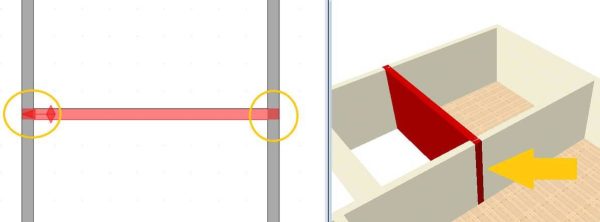
Example images for wall situations that can be automatically corrected with the tool
Walls that are too short: In such cases, a wall intersection / room formation is not possible
Overlapping Walls: When this is the case, additional segments are created from the face of the crossing wall on the opposite side of the wall. These undesired segments may be taken into account when creating the room and then lead to problems identifying the room contour.
Walls that are too long in corner situations: such cases can lead to problems, for example, when calculating the automatic ceilings or when determining the building contour (to create an opening in the terrain).
The 2D drawing functions under 2D & Layout have been expanded to include isosceles and equilateral triangles. Triangles are often used as part of technical symbols. With this new function you avoid the time-consuming construction of triangles using 2D polygons. Isosceles and equilateral 2D triangles can now be constructed with just a few clicks.
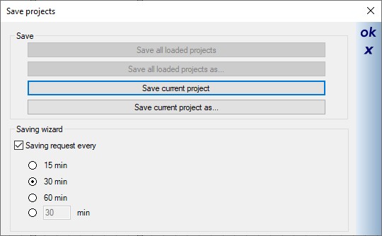 Automatic saving is not always helpful, especially with very large plans and short periods of time. Instead, we added a reminder function which displays the following dialog with buttons for saving.
You can then decide for yourself whether you want to save now or whether you close the dialog.
The buttons are offered with the following variants:
- Save current project: saves the project with the same file name
- Save Current Project As: opens the Save As… dialog so you can save the project with new names, i.e. basically creating a copy of the project, which is highly recommended.
You can also find the settings for the saving wizard in our “Settings ⇾ Program” menu on the “Messages & dialogs” page.
Für das Kopieren und gleichzeitige Spiegeln eines Gebäudes gibt es unter dem Menüpunkt “Bearbeiten ⇾ Gebäude bearbeiten” eine neue Funktion. Das Kopieren der gespiegelten Version eines Gebäudes erfolgt unmittelbar, nachdem Sie die Funktion aufgerufen und die Spiegelachse eingegeben haben. Halten Sie während der Eingabe der Spiegelachse die STRG-Taste gedrückt, um den exakten vertikalen oder horizontalen Verlauf der Achse zu gewährleisten.
Beachten Sie, dass nicht alle Elemente gespiegelt und kopiert werden können. Dazu gehören unter anderem Dächer und
Bemaßungen. Diese müssen nach dem Spiegeln neu erzeugt bzw. neu eingegeben werden.
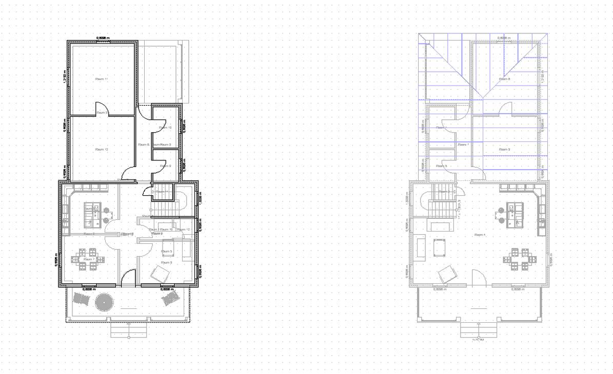
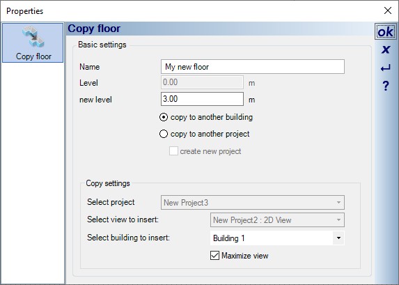
There is now a new function for copying an existing floor into a new building (within the same project) or into an existing building of another project, which can be conveniently executed via a dialog. You can find the dialog under “Edit ⇾ Edit building ⇾ Copy current floor”.
In the copy dialog you can copy the active floor to a new building and give the future floor a new name. At the same time, you determine the level at which it is to be inserted in the new building.
Below are screenshots of the dialogs for copying a floor within a project and for copying a floor to another project (new or existing) that is open at the same time.
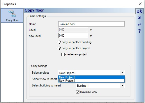
After the settings have been confirmed in the dialog with OK, the floor appears at the cursor and only has to be positioned accordingly in the selected view. If adjacent floors are included in the selected building, you should adjust the levels for the adjacent floors manually (select the “do not move” option in the dialog for adjusting the floors)


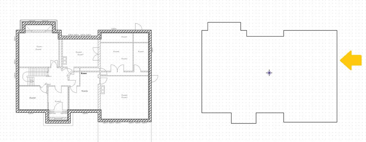
The comfortable moving of floors is now possible with just a few clicks. After calling up the “Move current floor” function under the “Edit ⇾ Edit building” menu item, the software tries to summarize the outer contours of the walls and “add” them to your mouse cursor as a preview.
By pressing the shortcut key CTRL-W you toggle between the corner points of the outline and then position the floor plan at the desired position.
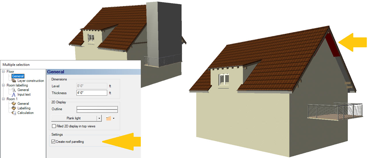
By default, a roof panelling is automatically generated by the rooms themselves and form a surface below the wooden structure of the roof.
In the past, these elements were created with an unwanted solid for those areas not covered by a roof/roof surface (e.g. protruding balconies, terraces). We have now changed this procedure so that the roof panelling is only formed for the area under the roof and the rest of the “room” or its surface is omitted. In addition, the roof panelling for a room can be completely deactivated in our room properties “Floor ⇾ General”.
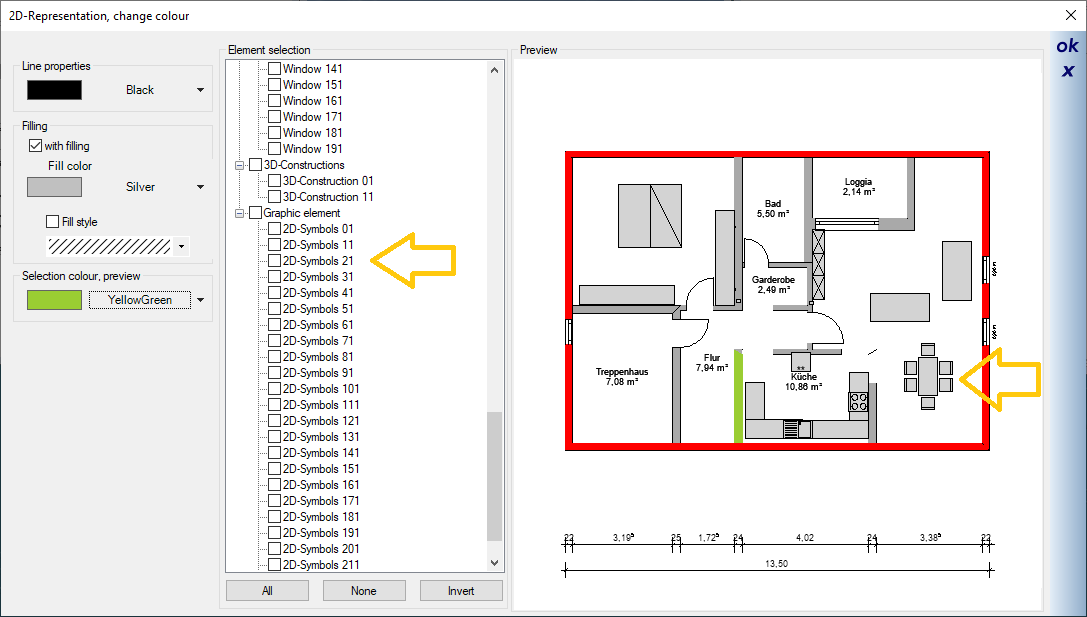
Coloring 2D symbols works similarly to coloring walls, windows and doors.
For example, you can place all electrical symbols on a separate layer and then color them in red with just a few clicks. Or you color 2D symbols of the facility in the desired color.
For large projects with an intensive layer structure, setting visibilities in views can be time-consuming. Now you can take over visibilities settings from another views. In the context menu of the desired view, for which the visibilities should be changed, there is now the option “Apply visibilities of a view…”
The desired (current) view not only adopts the visibility settings of individual elements, but also sets the buildings, floors and layers in our project viewer visible or invisible.
So far, 2D symbols were always created directly via the “Save as…” dialog and only the file name could be specified. In the absence of an alternative, this file name was then also used for the display in the catalogue.
As with other elements, you can now also specify the file name and a so-called logical name for display in the catalogue. The logical name can therefore also contain characters that are better avoided in file names.
- Corrected: The rafters of cornice boxes shimmered through in 3D.
- Changed: Skylight sill heights are now displayed relative to the floor (previously 0 level)
- corrected: Purlin roofs saved as a group sometimes caused problems when separating the groups
- Corrected: The height above sea level was displayed without decimal places in the properties for elevation marks
- corrected: In the case of imperial display, the selected walls and the measuring tool were rounded too imprecisely.
- fixed: openings were wrongly assigned after splitting walls.
- New: layers can now optionally ignore all elements in other slides (important for wall intersection and room calculation)
- corrected: various problems when mirroring elements and buildings.
Additional features of cadvilla version 11
The additional features of cadvilla V11 listed in the following table only represent the most important changes compared to cadvilla V10. Of course, many other smaller modifications and enhancements, as well as the elimination of certain weak points, have also been implemented.
Legend for the following table:
![]() ,
,![]() – Feature is included in this version
– Feature is included in this version
![]() ,
,![]() – Feature is not included in this version
– Feature is not included in this version
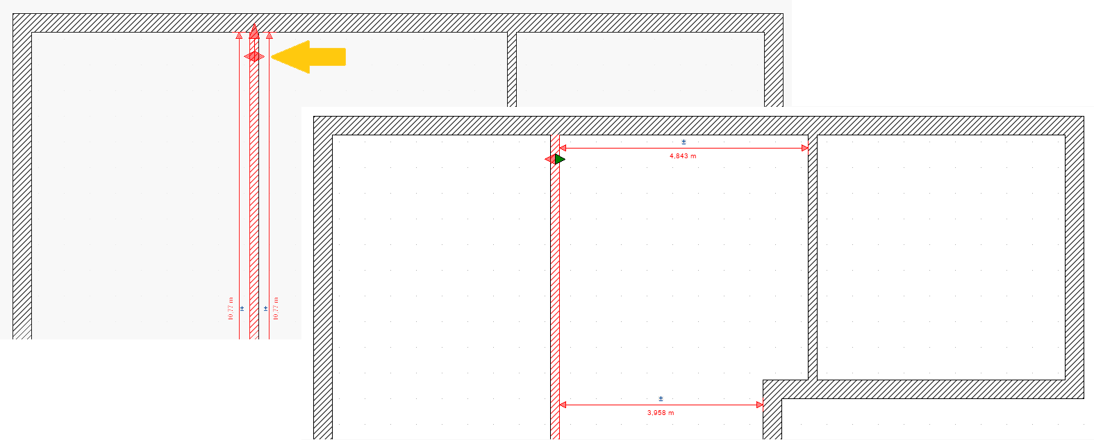 A convenient function has been added to the numerical positioning of interior walls. Since version 10, dimension chains with a button for numerically lengthening or shortening have been displayed when a wall is selected. Now walls also show a button as a double arrow. This button works alternately in the direction of the arrows.
By clicking on one of the arrows, the length dimensions of the selected wall disappear and one or more dimensions are displayed in the direction of the green arrow. The positioning of the wall is then carried out as usual by clicking on the +/- symbol and entering the desired dimensions.
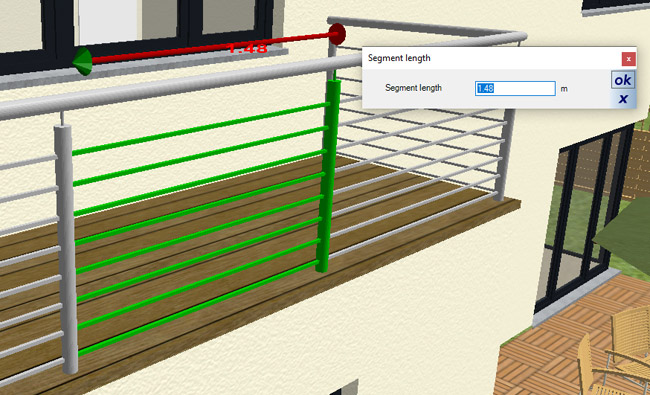
 A railing is inserted polygonally. After inserting the polyline, the railing dialog opens. Among other things, the desired standard segment for division along the polyline needs to be defined. The categories for defining the standard segment are divided into post, filling and handrail (link below).
After defining the railing segment, the railing is created along each polygon side. The division of the polygon sides into the desired segments is influenced by the input direction of the railing. At the end of each polygon side, a shorter segment is automatically added to fill the polygon side.
Alternatively, you can even the division of segments across the respective polygon sides. In addition to the segments with a specified length, 2 remaining segments of the same length are automatically created on each side of the railing. You can specify whether these should be shorter or longer than the standard segments (with a specified length).
 Railing segments of an automatically created railing can be individually selected and edited. In this case that means giving a segment a length that deviates from the usual division or using other filling properties. Other elements such as
 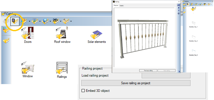 The settings of a completely designed railing can be saved as a template in a separate catalog. Internally, these templates are referred to as “railing project”. This allows you to quickly load railing settings once you have defined them for use in future projects, without having to redefine everything beforehand. Of course, a created “railing project” can also be helpful in the same building project by using this template for other railings within the same project.
Some example railings are already included in the railing catalog.
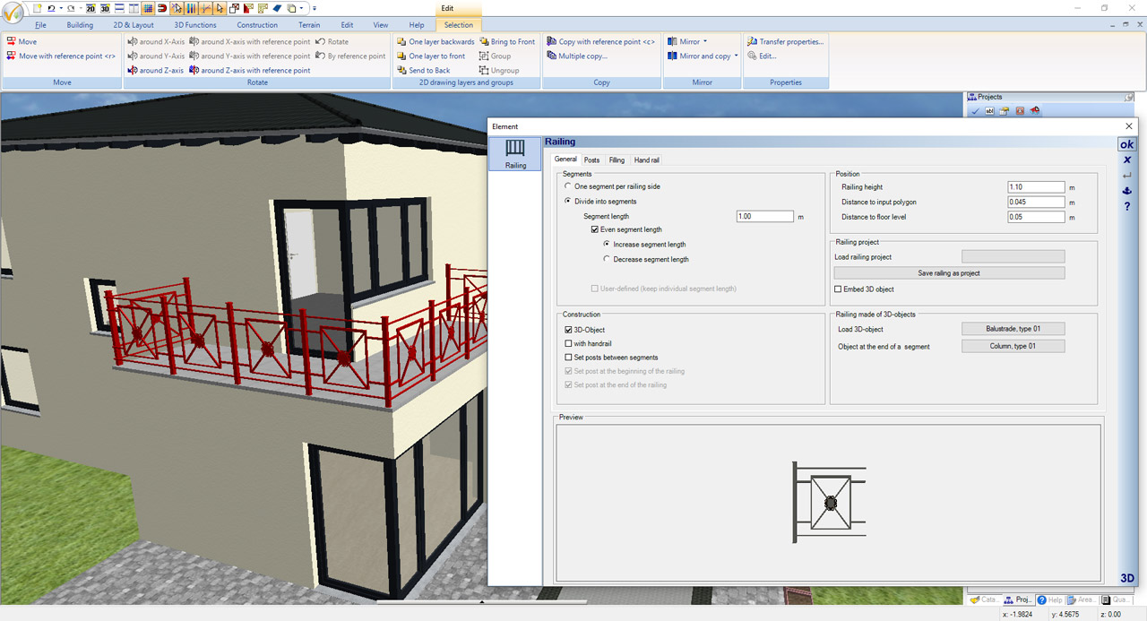 In addition to the configurable railings, there is now also the option of creating a railing using a finished 3D object from the catalogue. To do this, you simply let the selected 3D object follow the defined course of the railing and line it up. When changing textures, however, this does not go beyond saving and loading the project. When loading, the original 3D objects are retrieved from the catalog and assembled into a railing based on the parameters.
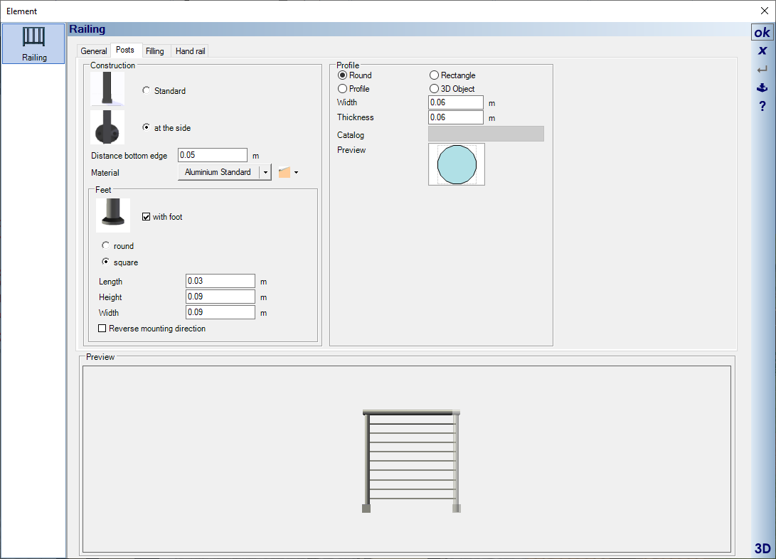 Posts of the railings can be made of 2D profiles or posts from catalog 3D objects.
posts made of profiles:
For posts made of profiles a round or rectangular profile is predefined as an option. Alternatively, other profiles from the profile catalog can also be used. Creating your own profiles from closed 2D polygons is only possible from cadvilla professional plus.
Posts from 3D Objects:
When using the “Posts from 3D Objects” option, select a post from the 3D Objects catalog in the Components -> Railings -> Posts directory.
The mounting options “Standard” and “at the side” are available for fastening the profiles. The value in the “Distance bottom edge” definition field extends the post downwards, with the railing height remaining the same.
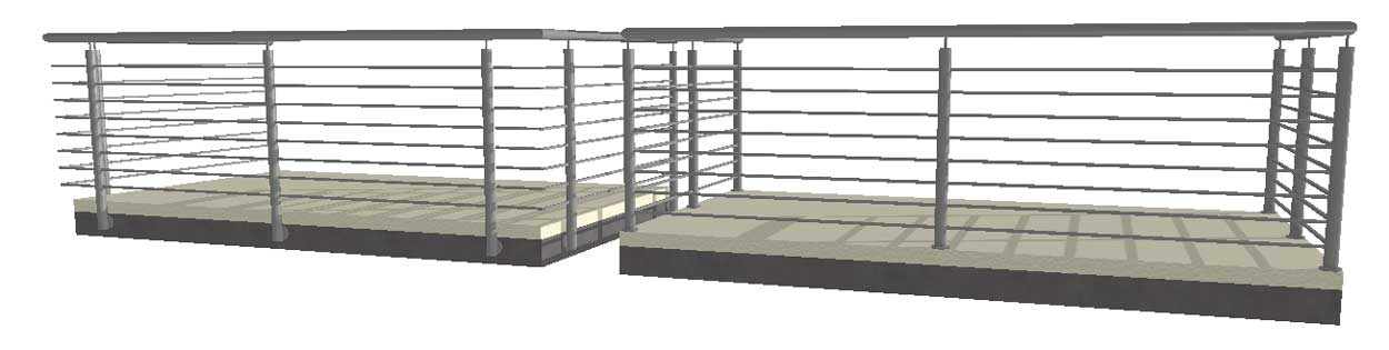
 Handrails are created from profiles along the entire length of the railing. The shape of the handrail is determined by selecting a profile from the profile catalog. Of course you can also draw your own profiles from closed 2D polygons and use them in the catalog (from cadvilla professional).
“Standard” and “with handrail connector” options are available for fastening the handrail. The distance from the handrail to the post is specified by the “Connector Height” value. The overall height of the railing remains the same.
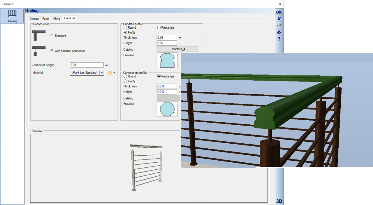
Fillings are available in three variants.
- Fillings with horizontal bars
- fillings with vertical bars
- so-called fixed fillings
In addition to the parameterized components of a filling made of horizontal or vertical bars, you can also choose ready-to-use 3D objects from our catalog under “Components → Railings → Bars”.
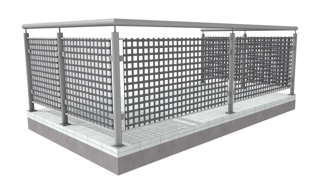 Fixed fillings consist of a simple 3D solid with a glass material by default. Of course, the material can also be replaced with another variants from the texture or material catalog using drag and drop.
Other possible materials also include so-called mask textures, some of which are located under the “mTextur -> Metal” directory. With such mask textures you can make a solid filling appear like a wire mesh, which is much more efficient than creating each wire individually as a 3D element.
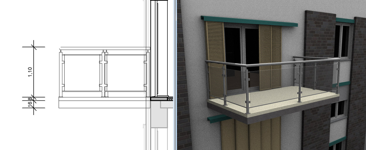 The balconies in the group catalog consist of a base plate and a railing. The floor slab was assembled from two extrude solids (one as a “replacement” for the ceiling and one as a covering). A predefined railing was positioned on it.
The construction of the balconies is 16 cm thick of the floor slab, which corresponds to the standard thickness of our ceilings, 8 cm covering and railing height 1.10 m.
The level of the ceiling slab is – 16 cm relative to the floor level. So if you insert one of the finished balconies in a 2D plan view, ideally it will automatically position itself correctly.
As with all groups in cadvilla, the parameters used can be changed at any time after the group has been separated into its individual components
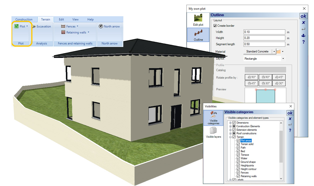 A new feature for creating plots has been added to the terrain tools. A property outline is entered as usual in the 2D view using a polygon, a rectangle or a spline. Multiple plots can be defined per project. Ideally, however, you should make sure that they do not overlap or lie edge to edge.
An plot always consists of a 3D solid whose surface follows the 3D terrain. Height points and height lines outside the plot (but within the defined terrain) are also taken into account.
Since plots and terrain have separate visibility, the plots can now also be displayed without the entire terrain.
An automatic border can optionally be defined for each plot. The border is all the way around and leaves no gaps for driveways or paths into the property. It is intended to better represent a plot in 3D.
Similar to the plot function, you can also have an automatic border created for beds and terraces, e.g. to display curbs. In the case of curbs, for example, you determine the profile of the curbs, define the width and height of the selected profile and also specify a segment length.
 In the past, real walls (from the building ribbon) were occasionally used to design the garden, but this is generally unfavorable for a number of reasons. The reason for this lies in the properties of these walls. They always try to intersect with other walls, forming rooms with floors. This can lead to problems with space formation and other undesirable effects.
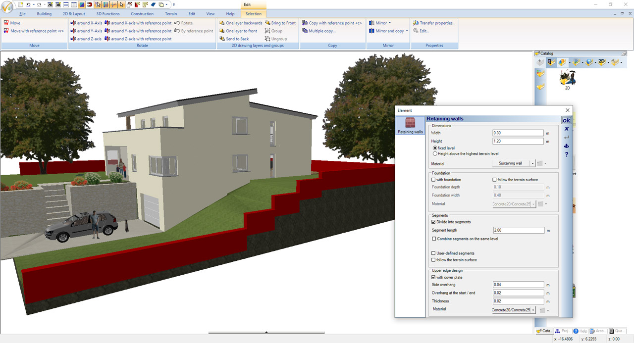
Now there is a new wall type for designing the garden on our “Terrain” ribbon. Whenever a wall is needed in the garden, a retaining wall should be used as standard. The only exception would be walls that also contain a door or window, or should be trimmed by a roof. In this case, the correct wall type to use would be a partition wall.
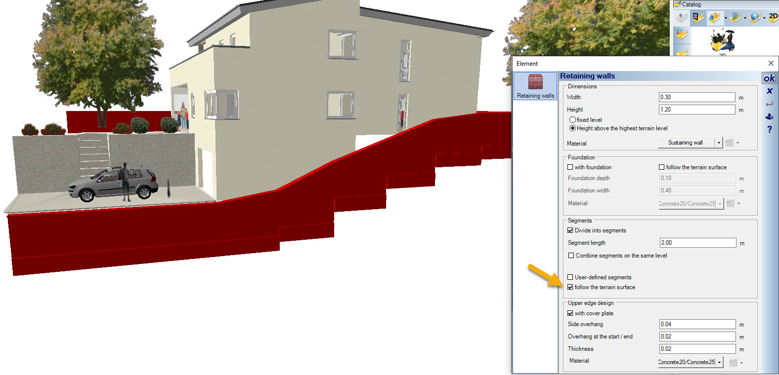 Retaining walls can be inserted polygonally or via a spline. After selecting the retaining wall function, open the properties dialog and first specify the wall width and height. If the retaining wall is made up of several individual wall segments, you can also specify a segment length for this. Other possible settings for the retaining wall are the generation of a retaining wall foundation and the automatic creation of a top slab. Retaining walls and foundations can also optionally follow the terrain.
Fences are essentially a variant of railings and contain similar creation options, but have different input tools and automatically follow the terrain surface depending on the input variant.
Similar to the railings, fences are also created in segments with adjustable length. At the end of each segment, i.e. where posts are typically placed, the fence determines the height of the terrain and adjusts the height accordingly.
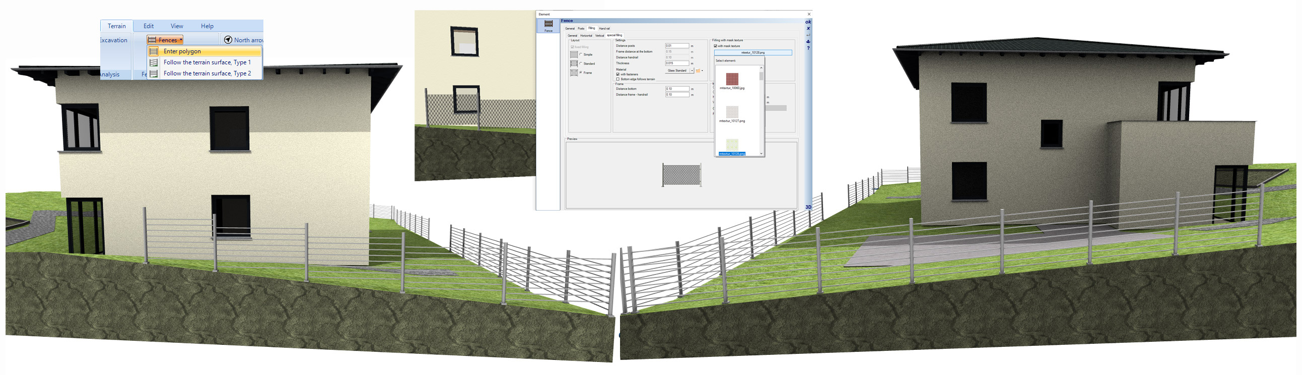
With variant 1, the fillings are calculated accordingly and are given a gradient from segment to segment, so that the height of the fence is measured at each post position and the spacing of the fillings fit at the top and bottom of the segment.
In variant 2, the filling remains horizontal and instead the posts are extended downwards and upwards. A stair-like look is the result.
To give a 3D fence the appearance of wire mesh, it’s best to use mask textures (similar to railing fillings). For fences we have added an additional selection button for the texture catalog.
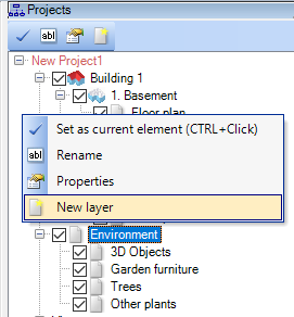
Now you can create further sub-layers in the Environment, similar to the project hiearchy. This is primarily used to sort elements without constructive influence. These include fences, retaining walls, plants and other 3D objects.
Note: Elements that have a constructive influence on the terrain – including height points, height lines, terrain shapes and areas, and properties – should not be sorted into sublayers. The visibility of such elements should be handled as before via the view’s visibilities settings and not via layers in the ENVIRONMENT.
 So far, the north arrow could only be rotated and moved manually via its properties dialog – and only if the ENVIRONMENT layer on which it is located was activated beforehand. Now there is a separate dialog for the north arrow settings on our “Terrain” ribbon. The dialog contains different options for positioning, rotating and scaling the north arrow.
By the way: the alignment of the north arrow influences the calculation of shadows in 3D views, provided that the calculation of the position of the sun is activated in the settings for internal light sources.
Übrigens: die Ausrichtung des Nordpfeils beeinflusst die Schattenbildung in den 3D Ansichten, sofern in den Einstellungen für die internen Lichtquellen die Berechnung des Sonnenstands aktiviert ist.
- more than 500 new 3D objects, mainly for office furnishings
- more 2D symbols with filled display
- additional features in release 11
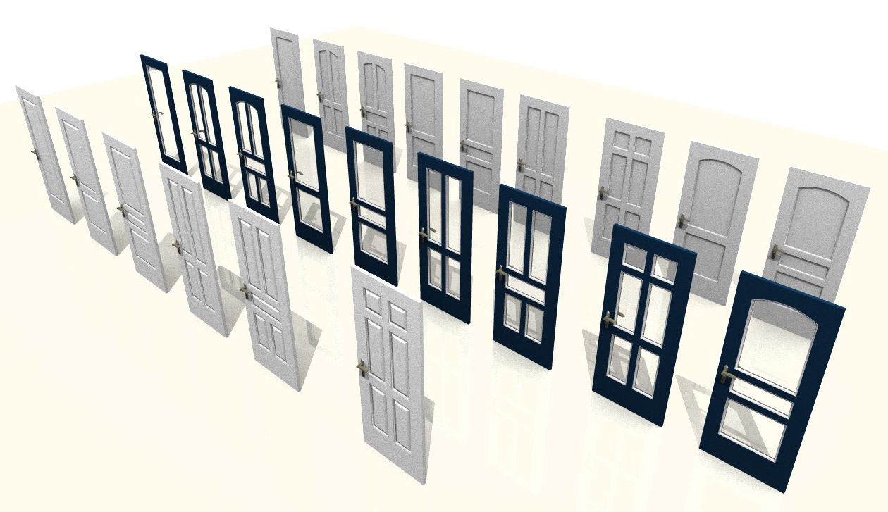
- more than 25 new interior doors
Additional features of cadvilla version 10
The additional features of cadvilla V10 listed in the following table only represent the most important changes compared to cadvilla V9. Of course, many other smaller modifications and enhancements, as well as the elimination of certain weak points, have also been implemented.
Legend for the following table:
![]() ,
,![]() – Feature is included in this version
– Feature is included in this version
![]() ,
,![]() – Feature is not included in this version
– Feature is not included in this version
While inserting walls, real-time dimensions are now displayed. Depending on how you work, these dimensions provide the exact length and are at the same time a visual control for identifying snap lines or grid points.
As soon as a wall is intersected with another wall, the interior and exterior dimensions are also displayed. (see our video on the right)
 With the new numerical tool, the real-time dimensions are also included, but more as rough overview. The real lengths is specified after the second mouse click.
In our standard tool for polygonal input via 2 points the second mouse click inserts the wall directly into the project. This is different in our new, additional input variant. With the second mouse click, a dialog appears in which the length and, if necessary, the angle can be numerically inserted and confirmed directly with ENTER. Inaccurate inputs due to unwanted movements with your mouse are no longer a problem.
The length in the dialog always refers to the currently active wall side, which is determined with CTRL + W during input.
With our “Tips for inserting walls” button you get the most important tips for inserting walls, such as CTRL + W to change the reference side, holding down the CTRL key to activate the angle grid and pressing the ESC key to exit the wall input.
 When a wall is selected, two dimensions and two buttons with ± appear.
Use these buttons to open the numeric input dialog in which you edit the exact length. Changing a wall lenght always applies in the input direction of the wall. This is marked by an arrow at the end of the wall (in our example on the right within the selected wall).
The previous lengthening or shortening of walls with our shortcut key V (also available via “Edit → Edit walls”) still works, of course, and can also be started by clicking on the red arrow at the end of the wall.
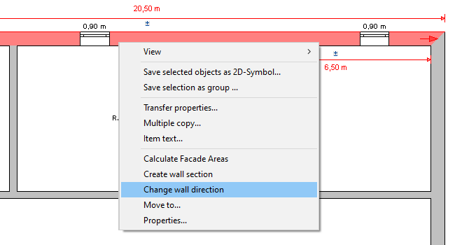 The numerical lengthening or shortening of walls always applies in the direction of a wall. The wall direction is marked by a red arrow inside the wall when it is selected.
You can now change this input direction via context menu of the right mouse button.
In addition, there is also the same option for changing a wall direction using the tool under “Edit → Edit walls”.
 In addition to the previous tools for inserting windows and doors, there is now another, extremely efficient option. This happens in two steps.
The first step is to position the window or door elements in the approximate position where they should be.
This is supported by additional real-time dimension lines – similar to the new wall tools. These dimension lines are only used for your orientation and not in order to achieve an exact positioning at that stage.
Our tip: By copying and then pasting windows or doors of the same type, you increase the input speed considerably. As soon as you have copied an opening element after selecting it with CTRL-C, you can insert it several times with CTRL-V at different positions and walls.
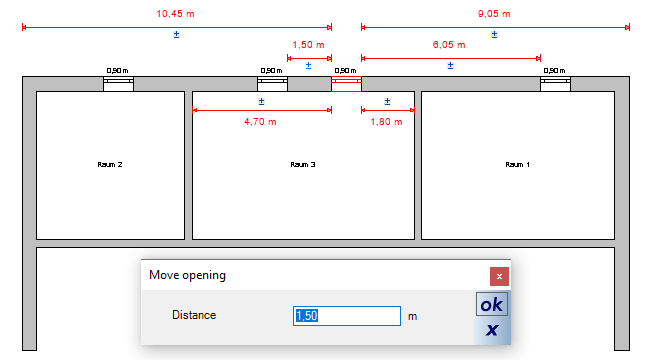 In a second step, you position your window or door numerically.
To do this, first select the opening element. Once selected, multiple dimensions related to the floor plan appear on your screen. These include the dimensions along the outer wall, measured from the left and right corners of the selected element. In addition, the dimensions of any interior walls and dimensions to the left and right of the next opening element appear.
A small ± button appears above each dimension line. Click on this button to open an input dialog in which you can specify the exact distance for the opening element.
Our dimensioning tools now contain two new menu items with which you can create automatic dimensioning drafts in 2D plan views. One is for automatic creation of dimensions for a single wall and the other automatic dimensioning of the entire floor plan.
The automatic dimensioning of the entire floor plan, all external walls and adjacent internal walls contained on the active layer are taken into account. In our new settings dialog you can specify which dimension chains should be generated automatically. The options are:
- Dimension of the total length of each side of the building
- External wall dimensions: if there is an offset in the facade
- Internal wall dimensions: includes the internal walls adjoining the external walls
- Dimensions for windows and doors
Once the dimension lines have been created automatically, the selected dimension types can be revised again separately for each side.

When generating the automatic dimensioning drafts, your floor plan is analyzed and the required dimension lines are generated depending on the floor plan layout. Regardless of the settings in the dialog, it can happen that you do not receive the four activated dimension lines, but only those that make sense. If there are no windows and doors on one side of the building or no offset in the facade (as in our example above), the software creates, for example, only three dimension lines instead of the predefined four.
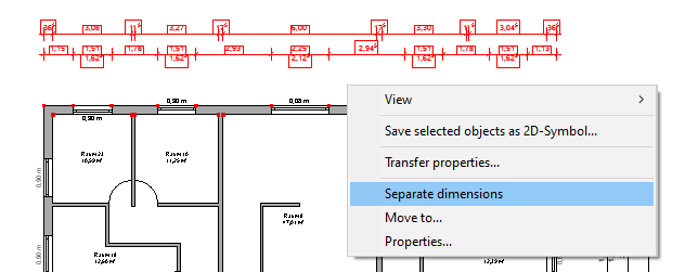 If the automatic dimensioning draft for a building side does not deliver the desired result, you can select it and separate it via context menu.
Now every single dimension line of the draft can be individually selected and changed according to your needs.
As with normal dimension lines, you can now delete individual dimensions, reposition them, or insert a manual dimension line instead.
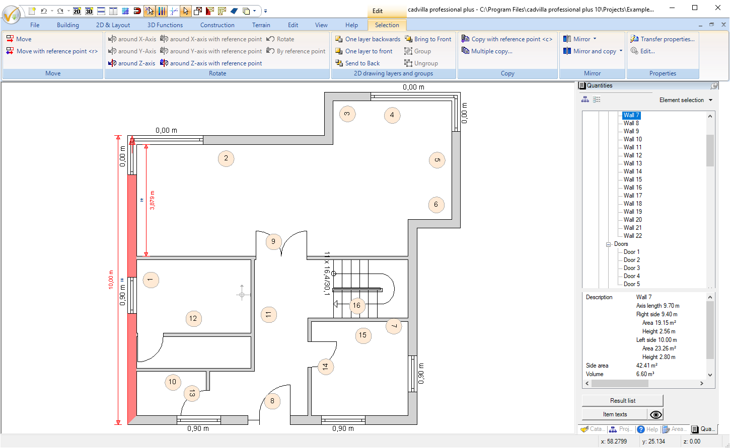
With the help of the automatic item texts, you can quickly establish a connection to the concurrent quantities plugin. Exactly the item numbers for walls and windows (optionally with associated description – e.g. wall) are automatically created within your drawing.
So if you need drawings in which you can immediately see in your floor plan which wall is meant by “Wall 1” and where it is located, you can simply generate the automatic item texts. Should one of these automatically generated texts be in an inconvenient position, it can be moved without any problems.
With this new function 3D objects from the Internet, 3D objects are imported directly into cadvilla in one step. This significant simplification enables you to work faster because the selection of the object, download, conversion and planning are all carried out in a single action.
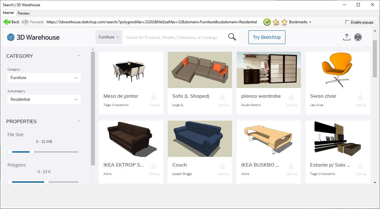
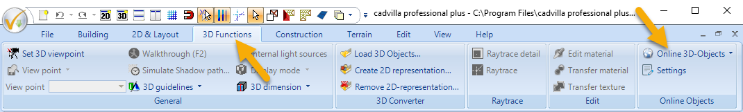 After calling up the menu item “Online 3D Objects” and selecting a preset website (e.g. 3D Warehouse, can also be freely defined), an internal browser window appears. Select an object and download it. From 3D warehouse, for example, you can import 3D models in Sketchup format (up to Sketchup 2020) or in Collada format directly into cadvilla.
After downloading a 3D object, a preview window opens with various setting options and a suitability test for cadvilla. The display of the 3D model is always as it would look like after importing it into our software.
Note: The quality and the representation always depend on the original model or the modeler of the 3D object. So if it’s not what you expected, stop here and take another item. With a click on “Insert object in your project”, you continue with positioning of the 3D model.
 Mit einem Klick auf die Schaltfläche “Objekt in die Planung einfügen” geht es gleich mit der Positionierung des 3D Modells innerhalb Ihrer Planung weiter.
With version 10, Sketchup formats (* .skp) 2017 to 2020 are also supported for converting into our own cadvilla format (* .cyg).
With version 10 we have added more than 200 new 3D objects to our standard catalog. The additions essentially concern the following catalog categories.
- 35 new doors , double doors, doors with side windows and external doors
- 14 cars
- more than 65 bathroom objects
- more than 90 3D objects for office interior
The 2D symbol catalog was extended with more than 250 additional, partly colored symbols:
- Living (cupboards, sofas, armchairs, stools, chairs)
- Sleeping room
- Furnishings
- Bathroom
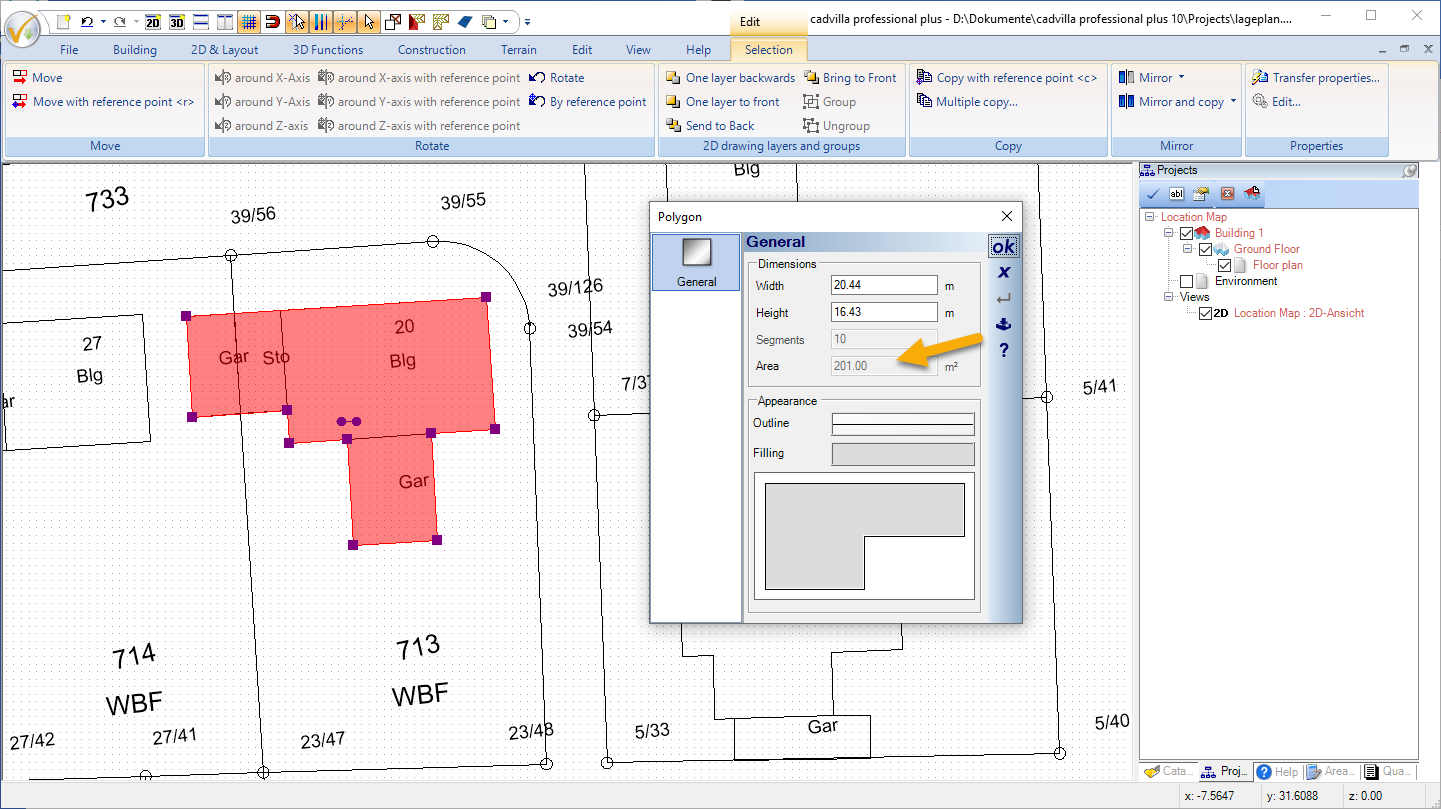
Closed 2D graphic elements are created with our 2D drawing functions on “2D & Layout“. These include rectangles, closed polygons, circles and ellipses. What is new with these functions is that the area for the drawn 2D graphic elements is now displayed in its properties dialog.
For example, you can now use the 2D drawing functions to trace an imported site plan, and after selecting an inserted polygon you will immediately know how many m² it covers.
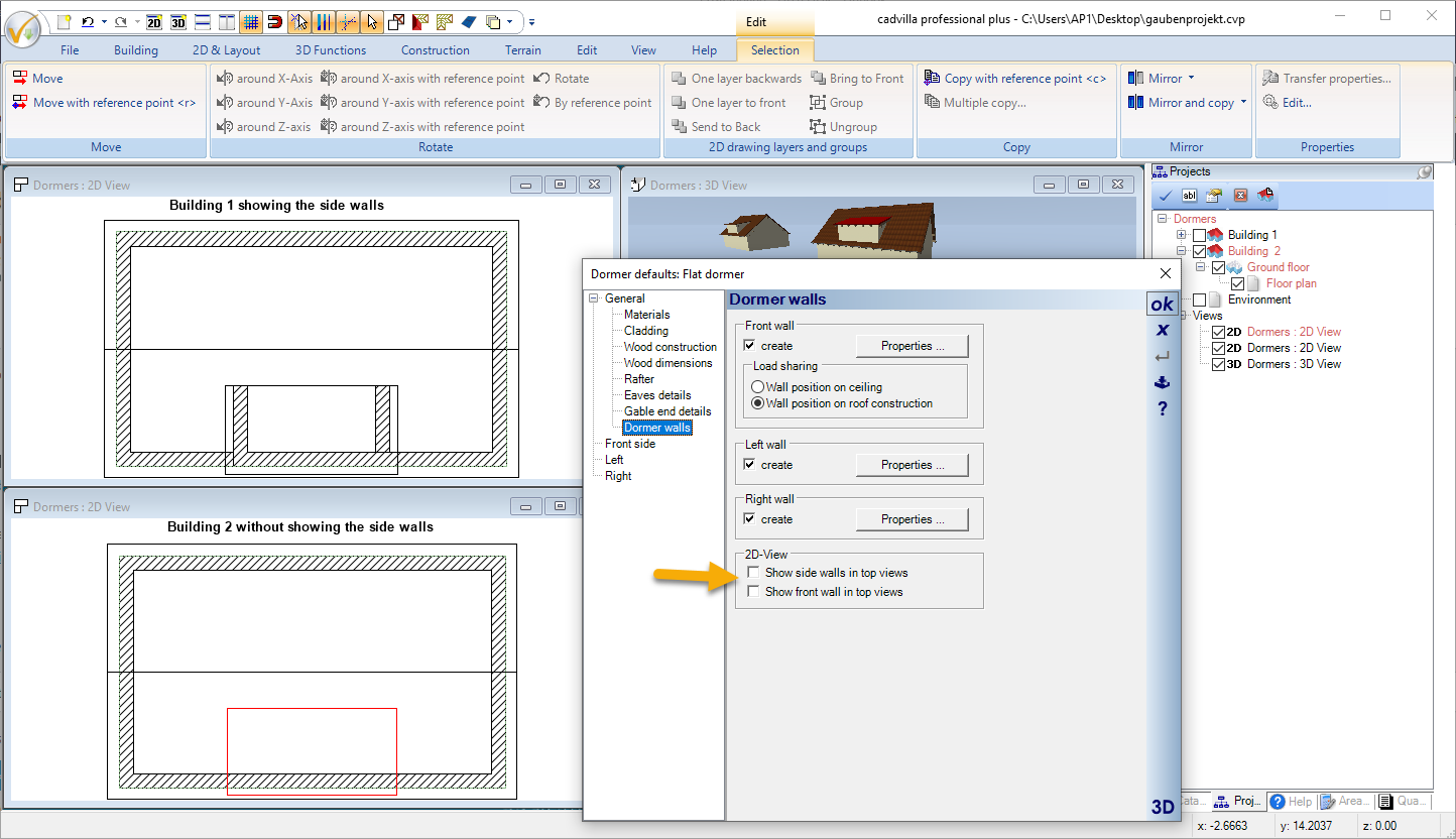
So far there was no difference in our program between dormer walls and normal walls. We have now changed that. The dormer dialog offers two new options for dormer walls.
- Show sidewalls in 2D top views
- Show front wall in 2D top view
The screenshot shows the previous display of dormers on the left and the dialog with the above options and the changed display in the 2D top view on the right.
- Lightweight and partition walls now only have one wall layer with a thickness of 10 cm.
- The list of recently opened projects now has 12 instead of 6 entries.
- When inserting windows in external walls, these are now always automatically set to opening inwards
- There is now one (project-based) option: Show all – all views
- The support dialog (under Help → Show support dialog → Repair functions), the excavation for all beds, terraces, bodies of water and paths in the project can be set to 0
- Properties can now also be transferred to terrain elements bed, terrace, water and path
- When inserting height points, the values of the last entered point is retained for new entries and the dialog accepts the data with ENTER.
- The handling of the cursoring when changing the size of elements in 2D has been simplified. Elements can now be moved or changed directly with the mouse.
- Scaling of 3D objects in 2D plan views with the mouse
- The selected path in the catalog can now be added to the favorites menu.
- Unnecessary room texts are now also deleted via “Remove invalid elements” in the support dialog.
- …
Upgrade your cadvilla or switch to a larger version of cadvilla
Would you like to expand the scope of your cadvilla version and upgrade to the latest version? Or would you like to switch from your existing cadvilla version to a larger version of cadvilla right away?
Additional features of cadvilla Version 2 – Version 13
Additional features of cadvilla Version 2 – cadvilla Version 5 are listed here.
Additional features of cadvilla Version 6 – cadvilla Version 9 are listed here.
Additional features of cadvilla Version 10 – cadvilla Version 12 are listed here.
Additional features of cadvilla Version 13 are listed here.